Node Editor
The Node Editor presents all the content that can be found within the dcd.xml file in an editing environment designed for ease of use.

Node Editor
To open the Node Editor, double-click a Device Configuration Descriptor (DCD) file from the Project Explorer view. The Node Editor contains an Overview, Devices, Diagram, and a raw XML tab, which contains the DCD file content.
Overview Tab
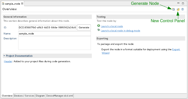
The Overview tab provides general information about the node with hyperlinks to additional node-related sections within the IDE.

Node Editor Overview Tab
In the top-right corner, the Generate Node button is used to generate supporting files for the node. To produce an RPM spec file for the node, click the button.
- The General Information section provides controls to set the ID, Name, and Description of the node.
- The Project Documentation section displays a Header hyperlink, which if clicked, provides the option to create and edit the file “HEADER” in the project. When code generation is performed, the header is applied to your project files.
- The Testing section is currently under development and is presently not supported.
- The Exporting section provides a hyperlink to the Export Wizard, which steps through the process of deploying the node into the SDRROOT.
Devices/Services Tab
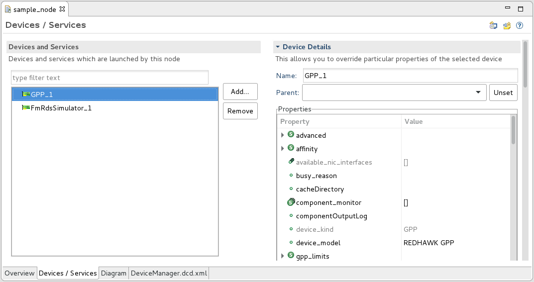
The Devices/Services tab enables a user to add devices and services from the SDRROOT into the node and to configure the properties for the devices and services. When a property is set or changed here, it is specific to this node and does not impact other nodes or instances of this device or service.

Node Editor Devices/Services Tab
The following steps explain how to add a device to the node:
Click Add….
Select the device or service to add.
Click Finish.
Use the table in the Details section to configure the properties of the device or service.
Diagram Tab
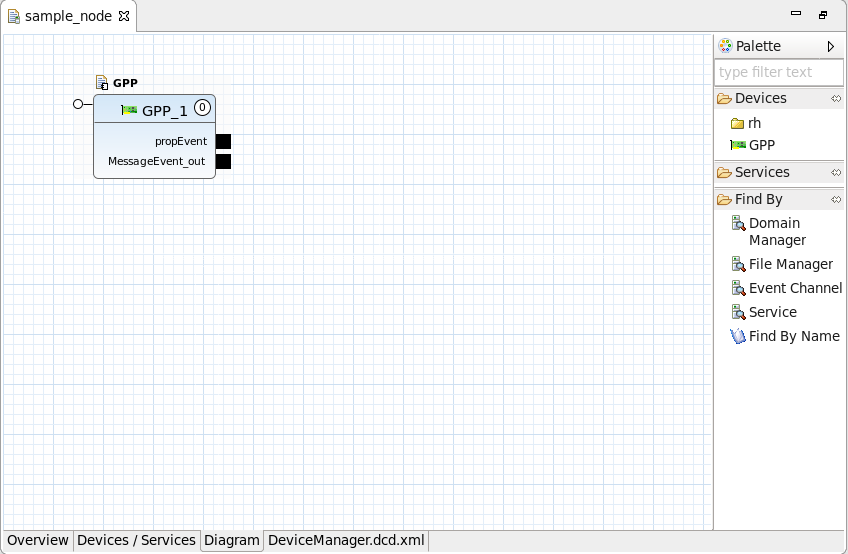
The Diagram tab enables a user to add devices and services from the SDRROOT into the node, configure the properties for the devices and services, and make connections.

Node Editor Diagram Tab
To zoom in and out on the diagram, press and hold Ctrl then scroll up or down. Alternatively, press and hold Ctrl then press + or -.
Adding a Device and Editing Device Properties in a Node
The following steps explain how to add a device to the node and configure its properties:
Drag the device from the Palette onto the diagram.
Select the device.
Open the Properties view and verify the Properties tab is selected.

Properties View
From the Properties view, change the desired properties.
Press
Ctrl+Sto save the changes.
If you want to quickly find a device in the Palette, you can replace the text type filter text in the text field at the top of the Palette with a keyword to filter the device list.
Like the Devices/Services tab, any property modified from the Diagram section is specific to this node and does not impact the device’s execution in other environments.
Editing the deployerrequires Set in a Node
The deployerrequires set for a Node is managed through the Requirements tab of the Properties view. When these Requirements are set, they become specific to the node and are written to the *.dcd.xml file.
The following steps explain how to edit the deployerrequires set.
- On the Diagram tab of the Node, select the Device
- In the Properties view, verify the Requirements tab is selected.

Properties View Requirements
- To add an ID and value, click + and add the ID and value. The ID and value can be any alphanumeric string value. This assigns a
devicerequireskey/value pair to the Node. - To remove an ID and value, select the ID and click X.
Using the Find By Feature
From the Diagram tab, a user may also use the Find By feature. The Find By feature enables a user to find a resource by name, a service by name or type, or an event channel by name.
Making Connections
Connections may be made from input to output ports by clicking and dragging from one port to the other. Ports may have more than one connection drawn to or from them. Any unsupported or erroneous connection detected by the IDE is marked with an appropriate indicator. Hovering over the indicator provides information concerning the error.
Start Order
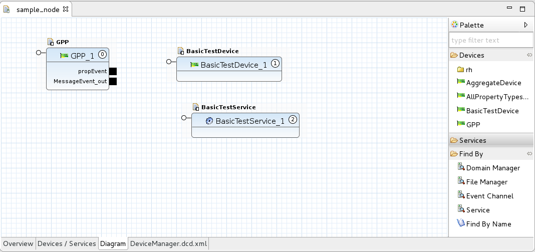
The Diagram tab also displays the start order of devices and services in the waveform. Start order represents the order in which its start() method is called by the Device Manager on startup, and the order in which its stop() method is called by the Device Manager on shutdown.

Devices/Services Start Order
Each of the devices/services within the node contains a number with a circle around it, which represents that device’s/service’s start order. The start order 0 is called first. Start order is optional and may be changed by right-clicking a device/service and selecting Move Start Order Earlier or Move Start Order Later from the context menu. Devices/services without a start order will not be started or stopped automatically.
The dcd.xml Tab
The dcd.xml tab displays the raw XML data, which describes the node fully. Although not recommended, manually editing the XML file is supported.
 REDHAWK