FrontEnd Interfaces
FrontEnd Interfaces (FEI) specify the interaction between applications and radio hardware. They include allocation, operation, and development of tuner devices within the REDHAWK Core Framework (CF). Tuner devices in this context may be Radio Frequency (RF), Intermediate Frequency (IF), or purely digital tuning equipment or software. Explicit types of tuners are defined, so that devices can be categorized by the capabilities they provide.
Tuner devices can provide individual tuners to other REDHAWK entities through tuner allocation. To allocate an individual tuner, the allocate() function of a device is called with an appropriate allocation structure as the only argument. Devices then allocate physical resources and, once a valid connection has been made, begin flowing data out of the device.
Physical devices often need to be split into multiple logical REDHAWK tuners to fully describe their functionality. Splitting physical devices often involves multiple tuners of the same, or mixed, types.
Common FEI Terminology
| Terminology | Description |
|---|---|
| device | A REDHAWK device. |
| FEI device | Devices that have a device_kind of FRONTEND and implement one of the FEI IDLs. Typically, GPS and navigation devices fall into this category. |
| tuner | A specific tuner capability in an FEI device. |
| FEI tuner device | Devices that have a device_kind of FRONTEND::TUNER. These devices must implement the TunerControl IDL and contain tuners for allocation. |
Required Properties for an FEI Tuner
| Name / ID | Description |
|---|---|
| device_kind / DCE:cdc5ee18-7ceb-4ae6-bf4c-31f983179b4d | Must be set to FRONTEND or FRONTEND::TUNER. |
| device_model / DCE:0f99b2e4-9903-4631-9846-ff349d18ecfb | Used to specify the model of the hardware device. |
| frontend_tuner_status / FRONTEND::tuner_status | A struct sequence where each struct in the sequence represents a single tuner. The structure is defined further in Tuner Status. |
Device Types
The set of FEI devices is:
- ANTENNA
- RX
- RX_ARRAY
- DBOT (Digital input Bank of Tuners)
- ABOT (Analog input Bank of Tuners)
- ARDC (Analog Receive Digital Channel)
- RDC (Receive Digital Channel)
- SRDC (Snapshot Receive Digital Channel)
- DRDC (Delay Receive Digital Channel)
- TX
- TX_ARRAY
- TDC (Transmit Digital Channel)
The following sections describe each device type in detail. The provided table describes the ports that are expected in each device type. The last column refers to a new allocation call that REDHAWK devices support that provides the caller with feedback; more on this later.
ANTENNA
The ANTENNA device is an analog receiver.
Minimum ports:
| Type | name | purpose | direction | description | returned by allocate() |
|---|---|---|---|---|---|
| RFSource | RFSource_in | data | provides (input) | Set of RF inputs that the antenna could switch to and the current RF input | No |
| RFInfo | RFInfo_out | data | uses (output) | RF information from the antenna to follow-on receivers | No |
RX
The RX device is an analog receiver.
Minimum ports:
| Type | name | purpose | direction | description | returned by allocate() |
|---|---|---|---|---|---|
| RFInfo | RFInfo_in | data | provides (input) | RF information from the antenna, such as rf_flow_id | No |
| RFInfo | RFInfo_out | data | uses (output) | RF information from the device to follow-on digitizers | No |
| AnalogTuner or AnalogScanningTuner | < any > | control | provides (input) | RF control such as setting center frequency | Yes |
RX_ARRAY
A device that aggregates multiple coherent receivers (RX, ARDC, or ABOT)
Minimum ports:
| Type | name | purpose | direction | description | returned by allocate() |
|---|---|---|---|---|---|
| DigitalTuner or DigitalScanningTuner | < any > | control | provides (input) | RF control such as setting center frequency | Yes |
DBOT (Digital input Bank of Tuners)
A device that contains a bank of tuners. The input for this device is a digital feed. Digitized channels are output through child devices (RDC, SRDC, or DRDC).
Minimum ports:
| Type | name | purpose | direction | description | returned by allocate() |
|---|---|---|---|---|---|
| DigitalTuner or DigitalScanningTuner | < any > | control | provides (input) | RF control such as setting center frequency | Yes |
| Bulk IO | < any > | data | provides (input) | Wideband digital feed into the device. | Yes |
ABOT (Analog input Bank of Tuners)
A device that contains a bank of tuners. The input for this device is an analog feed. Digitized channels are output through child devices (RDC, SRDC, or DRDC).
Minimum ports:
| Type | name | purpose | direction | description | returned by allocate() |
|---|---|---|---|---|---|
| RFInfo | RFInfo_in | data | provides (input) | RF information from the antenna, such as rf_flow_id | No |
| RFInfo | RFInfo_out | data | uses (output) | RF information from the device to follow-on digitizers | No |
| DigitalTuner or DigitalScanningTuner | < any > | control | provides (input) | RF control such as setting center frequency | Yes |
ARDC (Analog Receive Digital Channel)
An RX device with a wideband digitized output feed
Minimum ports:
| Type | name | purpose | direction | description | returned by allocate() |
|---|---|---|---|---|---|
| RFInfo | RFInfo_in | data | provides (input) | RF information from the antenna, such as rf_flow_id | No |
| RFInfo | RFInfo_out | data | uses (output) | RF information from the device to follow-on digitizers | No |
| DigitalTuner or DigitalScanningTuner | < any > | control | provides (input) | RF control such as setting center frequency | Yes |
| Bulk IO | < any > | data | uses (output) | Instance-specific wideband data feed. This is typically the whole RF bandwidth seen by the receiver. | Yes |
RDC (Receive Digital Channel)
RDC is a single received continuously digitized physical channel.
Minimum ports:
| Type | name | purpose | direction | description | returned by allocate() |
|---|---|---|---|---|---|
| RFInfo | RFInfo_in | data | provides (input) | Optional. RF information from the RX, ABOT, or DBOT (flow-through from the antenna), such as rf_flow_id | No |
| DigitalTuner or DigitalScanningTuner | < any > | control | provides (input) | RF control such as setting center frequency | Yes |
| Bulk IO | < any > | data | uses (output) | Digital data feed | Yes |
This device only exists as a child of either ABOT or DBOT
SRDC (Snapshot Receive Digital Channel)
SRDC is a single received snapshot digitized physical channel.
Minimum ports:
| Type | name | purpose | direction | description | returned by allocate() |
|---|---|---|---|---|---|
| RFInfo | RFInfo_in | data | provides (input) | Optional. RF information from the RX, ABOT, or DBOT (flow-through from the antenna), such as rf_flow_id | No |
| DigitalTuner or DigitalScanningTuner | < any > | control | provides (input) | RF control such as setting center frequency | Yes |
| Bulk IO | < any > | data | uses (output) | Digital data feed | Yes |
This device only exists as a child of either ABOT or DBOT
DRDC (Delay Receive Digital Channel)
DRDC is version of RDC that produced a single received time-delayed, continuously digitized physical channel.
Minimum ports:
| Type | name | purpose | direction | description | returned by allocate() |
|---|---|---|---|---|---|
| RFInfo | RFInfo_in | data | provides (input) | Optional. RF information from the RX, ABOT, or DBOT (flow-through from the antenna), such as rf_flow_id | No |
| DigitalTuner or DigitalScanningTuner | < any > | control | provides (input) | RF control such as setting center frequency | Yes |
| Bulk IO | < any > | data | uses (output) | Digital data feed | Yes |
This device only exists as a child of either ABOT or DBOT
TX
The TX device is an analog receiver.
Minimum ports:
| Type | name | purpose | direction | description | returned by allocate() |
|---|---|---|---|---|---|
| RFInfo | RFInfo_in | data | provides (input) | RF information from the processing flow | No |
| RFInfo | RFInfo_out | data | uses (output) | RF information for the antenna | No |
| AnalogTuner | < any > | control | provides (input) | RF control such as setting center frequency | Yes |
TX_ARRAY
A device that aggregates multiple coherent transmitters (TX)
Minimum ports:
| Type | name | purpose | direction | description | returned by allocate() |
|---|---|---|---|---|---|
| AnalogTuner | < any > | control | provides (input) | RF control such as setting center frequency | Yes |
TDC (Transmit Digital Channel)
TDC is a single transmit digitized physical channel.
Minimum ports:
| Type | name | purpose | direction | description | returned by allocate() |
|---|---|---|---|---|---|
| RFInfo | RFInfo_out | data | uses (output) | RF information for the TX (flow-through to the antenna), such as rf_flow_id | No |
| TransmitControl | < any > | control | provides (input) | RF control such as setting center frequency | Yes |
| Bulk IO | < any > | data | provides (input) | Digital data feed to be transmitted | Yes |
Note: If a system has a single TDC, then there is an implied TX stage, and the TDC can be connected directly to the antenna.
Multi-Channel Frontend Devices
Multi-channel devices provide a single point where different, often independent, RF devices operate. However, these devices are bound in the same enclosure, making them inter-linked in arbitrary ways. Further, independent channels may not be fixed in number, as in the case of a channelizer implemented on FPGA.
To model a workflow with multi-channel devices, the concept of child devices was developed for FEI 3.0. With child devices, a single device process space is used to associate multiple device class definitions. An example definition of child devices with respect to a parent device is shown in the following diagram:
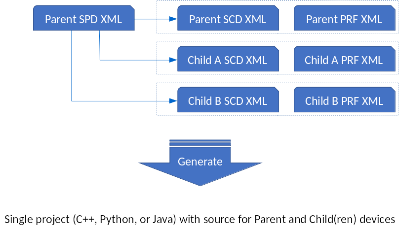
The parent and child devices are defined by three XML files: Software Package Descriptor (SPD), Software Component Descriptor (SCD), and Properties Definition (PRF). The parent SPD file contains a list of the different child SPD files. The generated code is a single project that contains all device classes.
Devices are deployed programmatically at runtime using the addChild method in the Device base class. The addChild method is invoked on the logical parent of the child device. For example, suppose that XML is defined for device "my_parent", "child_class_a", and "child_class_b". In C++, the children classes are generated in their own namespace to avoid naming conflicts in properties and to allow children to have a different frontend tuner status property than the parent. Then code generation would produce the following file tree:
my_parent
|   my_parent.spd.xml
|   my_parent.scd.xml
|   my_parent.prf.xml
|   child_class_a.spd.xml
|   child_class_a.scd.xml
|   child_class_a.prf.xml
|   child_class_b.spd.xml
|   child_class_b.scd.xml
|   child_class_b.prf.xml
|   reconf
|   configure.ac
|   Makefile.am
|
|---cpp
|   |   my_parent.cpp
|   |   my_parent.h
|   |   my_parent_base.cpp
|   |   my_parent_base.h
|   |
|   |---child_class_a
|   |   |   child_class_a.cpp
|   |   |   child_class_a.h
|   |   |   child_class_a_base.cpp
|   |   |   child_class_a_base.h
|   |
|   |---child_class_b
|   |   |   child_class_b.cpp
|   |   |   child_class_b.h
|   |   |   child_class_b_base.cpp
|   |   |   child_class_b_base.h
After expanding the previous example so that child_class_a is the parent of a second instance of child_class_b, the code in my_parent.cpp would contain:
#include "child_class_a/child_class_a.h"
#include "child_class_b/child_class_b.h"
// this device instantiation code was added to the constructor, but it does not need to be added there
void my_parent_i::constructor()
{
std::string child_class_a_name("child_class_a");
std::string child_class_b_name("child_class_b");
child_class_a::child_class_a_i* first_layer_a = this->addChild<child_class_a::child_class_a_i>(child_class_a_name);
child_class_a::child_class_a_i* first_layer_b = this->addChild<child_class_a::child_class_a_i>(child_class_b_name);
child_class_a::child_class_a_i* second_layer_b = first_layer_a->addChild<child_class_a::child_class_a_i>(child_class_b_name);
}Each Device has a member named _dynamicComponents, with handles to each of its children. Below is an example of using _dynamicComponents:
for (unsigned int i=0; i<_dynamicComponents.size(); i++) {
    child_class_a::child_class_a_i* base_dev = dynamic_cast<child_class_a::child_class_a_i*>(_dynamicComponents[i]);
    std::cout<<"  "<<_dynamicComponents[i]->_identifier;
    if (base_dev == NULL) {
        std::cout<<" is not of type child_class_a::child_class_a_i";
    } else {
        std::cout<<" is of type child_class_a::child_class_a_i";
    }
    std::cout<<std::endl;
}
The vector _dynamicComponents is public, so a particular device's children can be inspected by other classes. Thread-safe changes to _dynamicComponents are managed through the DynamicComponent base class's _dynamicComponentDeploymentLock member.
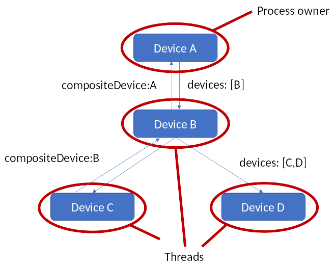
Through the Aggregate device interface, each device has access to its parent and children. The following code demonstrates this access with a different arrangement of devices.
from ossie.utils import redhawk
dom = redhawk.attach()
DeviceA = None
for dev in dom.devMgrs[0].devs:
    if dev.name == 'DeviceA':
        DeviceA = dev
        break

DeviceB = DeviceA.devices[0]

DeviceC = DeviceB.devices[0]
DeviceD = DeviceB.devices[1]

up_DeviceB = DeviceC.compositeDevice
up_DeviceA = up_DeviceB.compositeDevice
The relationship above is shown graphically, below:
Device Kinds
The device_kind property is used to ease the identification of candidate devices, reducing the search scope. The possible device_kind property values that should be used is as follow:
| value | description |
|---|---|
| FRONTEND::PARENT | This device has FEI children |
| FRONTEND | This is an FEI device |
| FRONTEND::GPS | Device that originates GPS information |
| FRONTEND::NAVIGATION | Device that originates Navigation information |
| FRONTEND::RFINFO | Device that originates RF Info (i.e.: an antenna) |
SRI and Keywords
FrontEnd devices use both the basic BulkIO SRI fields and the Keywords field for additional items. All standard SRI fields are filled out as appropriate in accordance with the existing BulkIO IDL descriptions. The following table describes the specific keywords for FrontEnd devices.
| Name | Type | Description | Notes |
|---|---|---|---|
| COL_RF | double | Collector center frequency in Hz. | Center frequency of the collector, which is typically thought of as the center frequency of the wideband receiver used to generate the IF data. In the case of an RDC, the value of COL_RF is the center frequency of the input to the RX. |
| CHAN_RF | double | Channel center frequency in Hz. | The center frequency of the stream. The value of CHAN_RF is equal to the COL_RF for RX, ABOT, or DBOT tuners but should still be included. |
| FRONTEND::BANDWIDTH | double | Effective bandwidth in Hz. | The effective bandwidth of the stream. |
| FRONTEND::RF_FLOW_ID | string | RF Flow ID of data. | Always include even if the RF Flow ID is blank. |
| FRONTEND::DEVICE_ID | string | The ID of the device. | Component ref ID, which allows downstream users to gain a reference to the device that created the data. |
| FRONTEND::ALLOCATION_ID | string | The allocation ID for this data. | In cases where the data in the stream is generated by a FrontEnd device, this is allocation ID corresponding to the generated data |
| FRONTEND::PATHDELAY | double | Path delay for the RF data | Measured RF path delay (from calibration) |
| FRONTEND::TDOA_SIGMA | double | Time difference of arrival sigma in seconds | Time difference of arrival sigma at this tuned frequency |
| FRONTEND::FDOA_SIGMA | double | Frequency difference of arrival sigma in Hz | Frequency difference of arrival sigma at this tuned frequency |
Parent/Child FEI Devices
In the context of FEI, it is possible to programmatically create device proxies that model the underlying hardware. For example, in the case where the configuration of the underlying RF hardware is not static and an API exists to scan the hardware, the following CONOP is enabled by the addChild API:
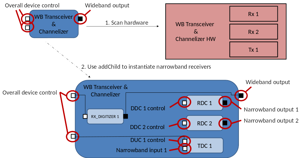
As seen in the example above, the underlying hardware is a transceiver with two receive channels and one transmit channel. Each devices is quasi-independent, sharing some common device control functionality, but each subsystem operating in a semi-independent fashion. Also notice that because the RDC share a single receiver, they need a common ABOT or DBOT, while the TDC does not require a TX device because there is only one TDC.
Note: the parent device (WB Transceiver and Channelizer) is not an FEI device. This device is a custom device that aggregates the underlying devices; in this case ABOT, RDC, and TDC. The parent device delegates the allocations to the child devices and can promote either ports or properties of the different child devices. Because allocations are returned with a reference to the child device satisfying the allocation (more on this in the next section), the parent device can be a custom device provided for convenience.
Allocations with feedback
Devices' capacity management interface has been extended to provide better support to sophisticated multi-device allocations. Single allocations can now be made through the allocate() call. The allocate() method is defined as follows:
struct PortDescription {
    Object port_ref;            // port object
    string name;                // port name
    string repository_id;       // port interface id (e.g.: "IDL:BULKIO/dataFloat:1.0")
};

typedef sequence <PortDescription> PortDescriptions;

struct Allocation {
    CF::Device device_ref;              // device that satisfied the allocation (the allocation could have been delegated)
    PortDescriptions data_ports;        // data ports ('provides' for TX, 'uses' for RX)
    PortDescriptions control_ports;     // control ports
    CF::Properties allocated;           // what allocation values the device met
    string alloc_id;                    // unique identifier (used to deallocate)
};
typedef sequence <Allocation> Allocations;

Allocations allocate(in CF::Properties capacities);
The allocate() method takes a sequence of properties as its argument and returns a sequence of Allocation structures. Each structure contains:
- a pointer to the device that satisfied the allocation request (which may or may not be the device the
allocate()call was made on) - a reference to the data port (if any) that relates to the allocation
- a reference to the control port (if any) that relates to the allocation
- the allocation values actually made on the device
- a unique allocation id
The Allocation structure returns the actual allocations because they may differ from the request. For example, in the case of a tuner, while a request may be for 12 kHz of bandwidth, if the device can only be configured to 12.5 kHz bandwidth, then the returned allocation value is 12.5 kHz. The amount of divergence between the requested and the actual value for the device parameter is controlled by the "tolerance" value in the allocation request. For example, if the requested bandwidth is 12 kHz and the tolerance is set to 10 (the value is in percent), then the maximum allowable returned value is 13.2 kHz.
All the structures returned in a single allocate() call relate to the same allocation. For example, if a coherent receive array is requested, the return value would contain an Allocation structure instance for each receive tuner that makes up the receive array. The unique allocation id, generated by the device responding to the allocation, populates every Allocation structure returned on the allocate() call. The receiver array example is described in more detail in the next section.
The data port reference is the data port associated with the allocation. For example, for a RDC allocation, the data port corresponds to the tuner's output port. Conversely, for a TDC allocation, the data port corresponds to the digital up-converter's data input port (to be transmitted over the air). If the allocation does not have a corresponding data transport, as in the case of generic processing resources, the data port reference is nil.
Like the data port, the control port reference is for the control port associated with the allocation. In the case of FEI, this could be a DigitalTuner port or a ScanningDigitalTuner port. If the allocation does not correspond to a controllable resource, the control port reference is nil.
Deallocation is based on the allocation id returned in the Allocation structures returned by allocate(). The deallocate() call is as follows:
void deallocate(in allocation_id);All devices that are associated with the given allocation id are deallocated. For example, if a phased array is allocated with n tuners, and the deallocate() call is made on any of the associated devices, then all of them are deallocated. In the case of such allocations where more than one device is allocated (such as in an array), the deallocate() call can be made against one of the single RDC devices to deallocate just that one device and not the others in the initial allocation.
Continuing with the example transceiver in the previous section, a single allocation made to the parent device can return the allocation of a single RDC, as shown below:
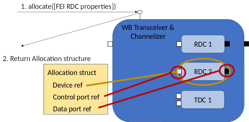
The return value from the allocation to the parent device is the child device's reference as well as its output data port and input control port.
Controlling Coherent Receivers (arrays) with Frontend Interfaces
When ingesting data from coherent tuners, allocations must be coordinated between multiple independent tuners; each of these tuners is associated with a different RF receiver and a different antenna. While each of these tuners is ostensibly independent, they must all be tuned to the same frequency over the same bandwith, with data generated coherently (in lock-step) between the different tuners.
The mechanism for supporting the process has a parent (aggregate) device for the array, and child devices for each receiver. Each receiver has a set of child devices: one for each tuner. In this case, each tuner (RDC FEI device) is a child of a wideband receiver (RX or ABOT FEI device), and each wideband receiver is the child of the array device proxy (RX_ARRAY FEI device).
The wideband receiver is an ABOT if it contains narrowband tuners, ARDC if it is a single channel, and RX if it does not. An ARDC is a combination of ABOT and a single RDC. Multiple receivers (RX, ABOT, or ARDC) can be combined into a coherent set, where the set is controlled by RX_ARRAY.
This device parent hierarchy is shown below:
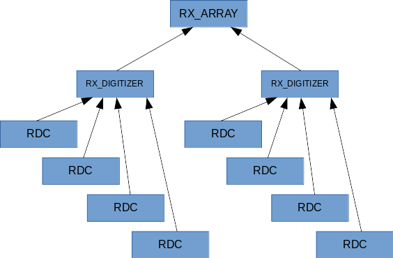
The programmatic deployment of this hierarchy uses the addChild() method built into each device. For example, the following code in rx_array.cpp shows a single RX_ARRAY (rx_array_i) creating two instances of ABOT (abot_i), each with 2 RDC (rdc_i).
#include "abot/abot.h"
#include "rdc/rdc.h"
// this device instantiation code was added to the constructor, but it does not need to be added there
void rx_array_i::constructor()
{
std::string abot_name("abot");
std::string rdc_name("rdc");
abot_ns::abot_i* abot_1 = this->addChild<abot_ns::abot_i>(abot_name);
rdc_ns::rdc_i* rdc_1_1 = abot_1->addChild<rdc_ns::rdc_i>(rdc_name);
rdc_ns::rdc_i* rdc_1_2 = abot_1->addChild<rdc_ns::rdc_i>(rdc_name);
abot_ns::abot_i* abot_2 = this->addChild<abot_ns::abot_i>(abot_name);
rdc_ns::rdc_i* rdc_2_1 = abot_2->addChild<rdc_ns::rdc_i>(rdc_name);
rdc_ns::rdc_i* rdc_2_2 = abot_2->addChild<rdc_ns::rdc_i>(rdc_name);
}As shown above, the device hierarchy is defined programmatically in the parent device, in this case the RX_ARRAY device. This relationship can be shown programmatically from the Python sandbox. For example, assuming that the Python session is attached to a domain with a deployment of the devices and node included in this project, the following code can be used to retrieve the array, the abot receivers, and the single-channel rdc tuners:
from ossie.utils import redhawk
dom = redhawk.attach()
agg_dev = None
for dev in dom.devMgrs[0].devs:
    if dev.name == 'rx_array':
        agg_dev = dev
        break
rx_d_1 = agg_dev.devices[0]
rx_d_2 = agg_dev.devices[1]

rdc_in_rx_d_1 = []
for dev in rx_d_1.devices:
    rdc_in_rx_d_1.append(dev)

rdc_in_rx_d_2 = []
for dev in rx_d_2.devices:
    rdc_in_rx_d_2.append(dev)
The parent device can be retrieved from any one child device.
for dev in dom.devMgrs[0].devs:
    if 'rdc' in dev.label:
        rdc_rx = dev
        break
rx_d = rdc_rx.compositeDevice
rx_array = rx_d.compositeDevice
For the array to function correctly, each wideband receiver must be connected to a different antenna. This antenna can be modeled with the GenericAntenna device, and its RFInfo port can be used to pass the rf_flow_id for that specific antenna element. To propagate the rf_flow_id, the rx_digitizer's output RFInfo port needs to be connected to each rdc's input RFInfo port. This functionality is not created by the code generators because it is CONOP-specific and must be implemented by the developer in the port's callback function. Note that this connection does not have to be defined in XML; instead it can be implemented programmatically when the devices are instantiated.
Allocating a tuner
Tuner allocations have remained unchanged from FEI 2.0.
| ID | type | description |
|---|---|---|
| FRONTEND::tuner_allocation::tuner_type | string | Device type |
| FRONTEND::tuner_allocation::allocation_id | string | Requested allocation id (empty string if does not matter). Will cause an error if not available |
| FRONTEND::tuner_allocation::center_frequency | double | Requested center frequency |
| FRONTEND::tuner_allocation::bandwidth | double | Requested bandwidth |
| FRONTEND::tuner_allocation::bandwidth_tolerance | double | Allowable percent above requested bandwidth (e.g.: 100 would be twice) |
| FRONTEND::tuner_allocation::sample_rate | double | Requested sample rate |
| FRONTEND::tuner_allocation::sample_rate_tolerance | double | Allowable percent above requested sample rate |
| FRONTEND::tuner_allocation::device_control | boolean | True: Has control over the device to make changes, False: marked as listening to device and wants to be notified when de-allocated |
| FRONTEND::tuner_allocation::group_id | string | Unique identifier that specifies the group a device must be in. Must match group_id on the device |
| FRONTEND::tuner_allocation::rf_flow_id | string | Specifies the RF flow of a specific input source to allocate against. Empty if the rf_flow_id does not matter |
Listener allocations are not needed (since there is a single data port per channel), but are still supported.
| ID | type | description |
|---|---|---|
| FRONTEND::listener_allocation::existing_allocation_id | string | Allocation to listen to |
| FRONTEND::listener_allocation::listener_allocation_id | string | Listener allocation |
Allocation extensions
The following allocations can be passed along with FRONTEND::tuner_allocation to specialize the allocation_id
The FRONTEND::snapshot allocation is used to specify snapshot parameters. The response to an allocation including FRONTEND::snapshot is an SRDC device
| ID | type | description |
|---|---|---|
| FRONTEND::snapshot_start::whole_seconds | double | J1970 GMT |
| FRONTEND::snapshot_start::partial_seconds | double | 0.0 to 1.0 |
| FRONTEND::snapshot_stop::whole_seconds | double | J1970 GMT |
| FRONTEND::snapshot_stop::partial_seconds | double | 0.0 to 1.0 |
The FRONTEND::delay allocation is used to specify time-delay parameters for the data feed. The response to an allocation including FRONTEND::delay is an DRDC device
| ID | type | description |
|---|---|---|
| FRONTEND::delay::whole_seconds | double | J1970 GMT |
| FRONTEND::delay::partial_seconds | double | 0.0 to 1.0 |
| FRONTEND::delay::relative | boolean | True if relative to now, false if absolute (UTC) |
The FRONTEND::stream_id allocation is used to request a particular stream id for the generated data sets. The response to an allocation including FRONTEND::strema_id is an RDC, ARDC, SRDC, or DRDC device
| ID | type | description |
|---|---|---|
| FRONTEND::stream_id::requested_stream_id | string | Requested stream id for generated data |
The FRONTEND::data_format allocation is used to request a particular data type for the generated data.
| ID | type | description |
|---|---|---|
| FRONTEND::data_format::bulkio_type | string | Repository ID for the requested type (e.g.: IDL:BULKIO/dataShort:1.0) |
| FRONTEND::data_format::mode | boolean | Set true for complex, false for real |
The FRONTEND::payload_format allocation is used to request the payload in the case of SDDS or VITA49 data sets
| ID | type | description |
|---|---|---|
| FRONTEND::payload_format::native_type | string | binary format (e.g.: float, short, short, ushort) |
| FRONTEND::payload_format::endian | boolean | Set true for big endian, false for little endian |
The FRONTEND::upstream allocation is used to require that the allocated device have a connection from the device specified
| ID | type | description |
|---|---|---|
| FRONTEND::upstream::device_id | string | device instance id for the upstream device |
Allocating a set of coherent channels
Unfortunately, some of the data structures needed to allocate an array are currently not available in the IDE. So the allocations must be made through a programmatic interface like the Python sandbox.
To allocate an array, the allocation property "FRONTEND::coherent_feeds" of type string sequence was created. The number of string elements in the sequence determines how many tuners (from different wideband feeds) need to be allocated for this request. If the value in each of these strings is not an empty string, then that specific set of rf_flow_id values must be matched. If each string is empty, then any of the wideband feeds can satisfy the request. Note that at most 1 tuner per wideband feed can be allocated in each request.
The following code allocates 2 tuners with 1kHz of bandwidth for rf_flow_id "aperture_1" and "aperture_2".
from ossie.utils import redhawk
import frontend
from ossie.cf import CF
from omniORB import any as _any

dom = redhawk.attach()
agg_dev = None
for dev in dom.devMgrs[0].devs:
    if dev.name == 'rx_array':
        agg_dev = dev
        break

alloc_tuner_1 = frontend.createTunerAllocation(tuner_type='RDC',
                                               allocation_id='alloc_id_1',
                                               bandwidth=1000.0,
                                               returnDict=False)
coherent_request = CF.DataType(id='FRONTEND::coherent_feeds',
                               value=_any.to_any(['aperture_1', 'aperture_2']))
allocation_response = agg_dev.allocate([alloc_tuner_1, coherent_request])
Deallocation requires the allocation id:
agg_dev.deallocate(allocation_response[0].alloc_id)The following code allocate 2 tuners with 1kHz of bandwidth for any rf_flow_id.
alloc_tuner_1 = frontend.createTunerAllocation(tuner_type='RDC',
                                               allocation_id='alloc_id_1',
                                               bandwidth=1000.0,
                                               returnDict=False)
coherent_request_any_feed = CF.DataType(id='FRONTEND::coherent_feeds',
                                        value=_any.to_any(['', '']))
allocation_response = agg_dev.allocate([alloc_tuner_1, coherent_request_any_feed])
To allocate scanning tuners, include a scanner allocation request. For example, assuming that a scanning functionality is needed where the scanner is expected to change frequencies above 10kHz, use the following:
alloc_scanner = frontend.createScannerAllocation(min_freq=10000.0, returnDict=False)
alloc_tuner_1 = frontend.createTunerAllocation(tuner_type='RDC',
                                               allocation_id='alloc_id_1',
                                               bandwidth=1000.0,
                                               returnDict=False)
coherent_request_any_feed=CF.DataType(id='FRONTEND::coherent_feeds', value=_any.to_any(['', '']))
allocation_response = agg_dev.allocate([alloc_tuner_1, coherent_request_any_feed])
If scanning functionality is needed, then each device's scan plan needs to be set independently, where the scan strategy is set for each device separately and the scan start time is set to some arbitrary time in the future.
Command and Control
Command and Control of existing allocated tuners is performed through the DigitalTuner or AnalogTuner port on the FEI device. These commands allow external users to get and set specific settings for each of the tuners. Each FEI tuner device must have a DigitalTuner port named DigitalTuner_in (or AnalogTuner_in for an AnalogTuner port) that allows for command and control. All of the functions in the tuner control interface need to be implemented even if only to report that the capability is not supported. Each of these tuner control interface functions uses the Allocation ID to uniquely identify the tuners.
NOTE: An output control port used to control an FEI device follows the same connectivity rules explained in Custom IDL Interfaces.
Tuner Control Interface
The tuner control interface describes two interfaces for control. The first is the AnalogTuner, which describes all of the functions common for Digital and Analog tuners. DigitalTuner inherits AnalogTuner and adds setOutputSampleRate() and getOutputSampleRate().
Tuner Control Functions
The following table describes the functions that can be accessed via the Tuner Control IDL.
| Function Prototype | Description |
|---|---|
string getTunerType(in string id) |
Get the type of tuner (e.g., RX or DDC) associated with this Allocation ID. |
boolean getTunerDeviceControl(in string id) |
Returns whether this Allocation ID has control (modification privileges) over the tuner. |
string getTunerGroupId(in string id) |
Retrieves the Group ID (may be empty) for this Allocation ID. |
string getTunerRfFlowId(in string id) |
Retrieves the RF Flow ID (may be empty) for this Allocation ID. |
CF::Properties getTunerStatus(in string id) |
Key/Value pair of entire tuner status structure. Note: The return is a sequence of simple properties, not a single struct property. |
void setTunerCenterFrequency(in string id, in double freq) |
Set the current center frequency in Hz. |
double getTunerCenterFrequency(in string id) |
Get the current center frequency in Hz. |
void setTunerBandwidth(in string id, in double bw) |
Set the current bandwidth in Hz. |
double getTunerBandwidth(in string id) |
Get the current bandwidth in Hz. |
void setTunerAgcEnable(in string id, in boolean enable) |
Enable or disable the Auto Gain Control (AGC). True indicates that the AGC should be enabled. |
boolean getTunerAgcEnable(in string id) |
Get the current status of AGC. True indicates enabled. |
void setTunerGain(in string id, in float gain) |
Set tuner gain in dB. |
float getTunerGain(in string id) |
Get current tuner gain in dB. |
void setTunerReferenceSource(in string id, in long source) |
Set the tuner reference source. Zero is defined as internal and one is defined as external. |
long getTunerReferenceSource(in string id) |
Get the current tuner reference source. |
void setTunerEnable(in string id, in boolean enable) |
Set the output enable state of the tuner. True indicates output is enabled. |
boolean getTunerEnable(in string id) |
Get the current output enable state of the tuner. True indicates output is enabled. |
void setTunerOutputSampleRate(in string id, in double sr) |
Set the output sample rate in samples/sec. |
double getTunerOutputSampleRate(in string id) |
Get the output sample rate in samples/sec. |
void configureTuner(in string id, in CF::Properties tunerSettings) |
|
CF::Properties getTunerSettings(in string id) |
Scanner Tuner Control Functions
The following table describes additional tuner control functions, which are present when the device is of type RX_SCANNER_DIGITIZER.
| Function Prototype | Description |
|---|---|
ScanStatus getScanStatus(in string id) |
Get the current scanner status. The return structure is of type FRONTEND::ScanningTuner::ScanStatus, which contains information on the scanning strategy, the scheduled start time, the list of center frequencies that the plan will execute, and whether or not the scan has started |
void setScanStartTime(in string id, in BULKIO::PrecisionUTCTime start_time) |
Schedule when a scan plan should start (in epoch time). Setting the time to 0 or a previous time with the tcstatus flag set to true starts a scan immediately. To disable the scan, set the start_time's tcstatus flag to false. |
void setScanStrategy(in string id, in ScanStrategy scan_strategy) |
Provide a plan for what frequencies the scanner will cover and how it will cover them. |
Tuner Control Exceptions
The following table describes exceptions that may occur during calls to tuner control functions.
| Exception | Description | Notes |
|---|---|---|
BadParameterException |
Parameter provided is invalid. | Indicates the value provided is out of bounds for the capability of the device or that the value was invalid (e.g., a negative frequency). |
NotSupportedException |
Capability is not supported. | Indicates the tuner does not support the setting (or getting) of this capability. |
FrontendException |
Generic FrontEnd exception. | Indicates there is a FrontEnd issue preventing the command, often because the Allocation ID does not match any currently allocated tuners. |
Scanning Interface
A scanning tuner requires a definition of how it should scan. This is provided with the ScanStrategy data structure.
ScanStrategy Description
The following table describes the members of the ScanStrategy data structure.
| Member | Type | Description |
|---|---|---|
scan_mode |
ScanMode |
ScanMode is an enumerated type that can be set to MANUAL_SCAN, SPAN_SCAN, or DISCRETE_SCAN |
scan_definition |
ScanModeDefinition |
ScanModeDefinition is a union that provides the mode-specific information: double center_frequency for MANUAL_SCAN, ScanSpanRanges freq_scan_list for SPAN_SCAN, and Frequencies discrete_freq_list for DISCRETE_SCAN |
control_mode |
OutputControlMode |
OutputControlMode is an enumerated type that can be set to TIME_BASED or SAMPLE_BASED |
control_value |
double |
This is the value for control_mode. The unit is seconds for TIME_BASED and samples for SAMPLE_BASED |
ScanSpanRange Description
The data structures Frequencies and ScanSpanRanges provide more detail for their respective modes. Frequencies is a sequence of doubles. ScanSpanRanges is a sequence of ScanSpanRange. The following table describes the members of ScanSpanRange.
| Member | Type | Description |
|---|---|---|
begin_frequency |
double |
The beginning center frequency for the scan in Hz |
end_frequency |
double |
The ending center frequency for the scan in Hz |
step |
double |
The change in center frequency in Hz |
GPS Interface
The GPS IDL provides an interface to retrieve GPS information from a device that is GPS-enabled. The GPS interface is composed of two attributes and no functions. However, the data structures returned by these attributes contain a large amount of detail.
NOTE: This interface's attributes are read/write, therefore, this interface can be used to read GPS information or to receive GPS information.
GPS Attributes
The GPS attributes are listed in the following table.
| Attribute Prototype | Description |
|---|---|
GPSInfo gps_info |
Get a detailed description of the GPS information on the device. |
GpsTimePos gps_time_pos |
Return the position generated by GPS as well as the timestamp for that position estimate. |
GPSInfo
The GPSInfo descriptions are listed in the following table.
| Member | Type | Description |
|---|---|---|
source_id |
string |
Device identifier for the device that generated the GPS location report (this device's ID if accessing the hardware directly) |
rf_flow_id |
string |
Identifier for the RF source (antenna) |
mode |
string |
"Locked" if the GPS Receiver has locked onto the signal, and "Unlocked" if the GPS Receiver has not locked onto the signal. Use "Tracking" if the GPS Receiver has found but not locked onto the signal (if available). |
fom |
long |
Position figure-of-merit (refer to the Figure of Merit table) |
tfom |
long |
Time figure-of-merit (refer to the Time Figure of Merit table) |
datumID |
long |
Identifier for the reference ellipsoid (datum). Use 47 for WGS 1984, the GPS datum |
time_offset |
double |
Receiver oscillator's most recent time offset (seconds). Usually 0 |
freq_offset |
double |
Receiver's center frequency offset (Hz) |
time_variance |
double |
Receiver oscillator's time offset variance (seconds |
freq_variance |
double |
Receiver's center frequency offset variance (Hz |
satellite_count |
short |
Number of satellites visible to the receiver |
snr |
float |
GPS receiver's reported signal to noise ratio. The definition of this value is not standardized and varies by manufacturer. |
status_message |
string |
Device-specific status message |
timestamp |
BULKIO::PrecisionUTCTime |
Timestamp for the GPS information |
additional_info |
CF::Properties |
Device-specific additional information |
Figure of Merit
The figure of merit (fom) provides the expected position error (EPE). The following table describes the possible values of the fom.
| Value | Error (meters) |
|---|---|
| 1 | less than 25 |
| 2 | less than 50 |
| 3 | less than 75 |
| 4 | less than 100 |
| 5 | less than 200 |
| 6 | less than 500 |
| 7 | less than 1000 |
| 8 | less than 5000 |
| 9 | greater than or equal to 5000 |
Time Figure of Merit
The time figure of merit (tfom) provides the expected time error (ETE). The following table describes the possible values of the tfom.
| Value | Error (nanoseconds) |
|---|---|
| 1 | less than 1 |
| 2 | less than 10 |
| 3 | less than 100 |
| 4 | less than 1e3 |
| 5 | less than 1e4 |
| 6 | less than 1e5 |
| 7 | less than 1e6 |
| 8 | less than 1e7 |
| 9 | greater than or equal to 1e7 |
GPS Interface Helpers
The GPS Interface helpers identify whether the GPS receiver has locked in on a signal or only found the receiver. The helper details are listed in the table below.
| Member | Value | Description |
|---|---|---|
GPS_MODE_LOCKED |
Locked |
GPS Receiver has locked onto the signal |
GPS_MODE_UNLOCKED |
Unlocked |
GPS Receiver has not locked onto the signal |
GPS_MODE_TRACKING |
Tracking |
GPS Receiver has found, but not locked onto the signal (optional) |
GpsTimePos
The GPSTimePos reports the location and the timestamp associated with the location report. The GPSTimePos details are listed in the table below.
| Member | Type | Description |
|---|---|---|
position |
PositionInfo |
Position report |
timestamp |
BULKIO::PrecisionUTCTime |
Timestamp for the location report |
GPS Support Types
The following table lists the type used by GpsTimePos for communicating position information.
| Member | Type | Description |
|---|---|---|
valid |
boolean |
The report is valid |
datum |
string |
Reference ellipsoid. Set to DATUM_WGS84 |
lat |
double |
Latitude (degrees) |
lon |
double |
Longitude (degrees) |
alt |
double |
Altitude (meters) |
NavData Interface
This interface provides basic navigational information such as position, velocity, and so forth. The NavData interface is composed of one attribute and no functions. While the interface returns a single attribute, that attribute contains multiple positional structures, some of which may not be supported by the navigation data source. Structures contain a "valid" flag, allowing the hardware to indicate whether or not the source provides that specific data set.
NOTE: This interface's attributes are read/write, therefore, this interface can be used to read navigation information or to receive navigation information.
NavData Attribute
The NavData attribute is used to retrieve additional detailed navigation information from devices.
| Attribute Prototype | Description |
|---|---|
NavigationPacket nav_packet |
Get detailed navigational information from the device. |
NavigationPacket
The NavigationPacket provides all of the detail required for communicating navigational information for a device.
| Member | Type | Description |
|---|---|---|
source_id |
string |
Device identifier for the device that generated the navigation report (this device's ID if accessing the hardware directly) |
rf_flow_id |
string |
Identifier for the RF source (antenna) |
position |
PositionInfo |
Location information in lat/long/altitude |
cposition |
CartesianPositionInfo |
Location information in x/y/z |
velocity |
VelocityInfo |
Velocity vector |
acceleration |
AccelerationInfo |
Acceleration vector |
attitude |
AttitudeInfo |
Attitude info (pitch/yaw/roll) |
timestamp |
BULKIO::PrecisionUTCTime |
Timestamp for the navigation data information |
additional_info |
CF::Properties |
Device-specific additional information |
NavData Support Types
The following tables list the types that are used by the NavigationPacket for communicating position, velocity, acceleration, and attitude information.
PositionInfo
| Member | Type | Description |
|---|---|---|
valid |
boolean |
The report is valid |
datum |
string |
Reference ellipsoid. Set to DATUM_WGS84 |
lat |
double |
Latitude (degrees) |
lon |
double |
Longitude (degrees) |
alt |
double |
Altitude (meters) |
CartesianPositionInfo
| Member | Type | Description |
|---|---|---|
valid |
boolean |
The report is valid |
datum |
string |
Reference ellipsoid. Set to DATUM_WGS84 |
x |
double |
X-axis (meters) |
y |
double |
Y-axis (meters) |
z |
double |
Z-axis (meters) |
VelocityInfo
| Member | Type | Description |
|---|---|---|
valid |
boolean |
The report is valid |
datum |
string |
Reference ellipsoid. Set to DATUM_WGS84 |
coordinate_system |
string |
CS_ECF (Earth-Centered Earth-Fixed), CS_ENU (East, North, Up), CS_NED (North, East, Down) |
x |
double |
X-axis (meters/second) |
y |
double |
Y-axis (meters/second) |
z |
double |
Z-axis (meters/second) |
AccelerationInfo
| Member | Type | Description |
|---|---|---|
valid |
boolean |
The report is valid |
datum |
string |
Reference ellipsoid. Set to DATUM_WGS84 |
coordinate_system |
string |
CS_ECF (Earth-Centered Earth-Fixed), CS_ENU (East, North, Up), CS_NED (North, East, Down) |
x |
double |
X-axis (meters/second^2) |
y |
double |
Y-axis (meters/second^2) |
z |
double |
Z-axis (meters/second^2) |
AttitudeInfo
| Member | Type | Description |
|---|---|---|
valid |
boolean |
The report is valid |
pitch |
double |
Pitch (degrees) |
yaw |
double |
Yaw (degrees) |
roll |
double |
Roll (degrees) |
RFInfo Interface
The RFInfo interface describes the contents of an RF feed (antenna/feed); the most direct analogy is that RFInfo describes a wire connecting an antenna to a tuner.
NOTE: This interface's attributes are read/write, therefore, this interface can be used to send RF feed information or to describe the RF feed information being received.
RFInfo Attributes
The RFInfo interface implements the attributes listed in the table below.
| Attribute Prototype | Description |
|---|---|
string rf_flow_id |
A string that uniquely describes the feed |
RFInfoPkt rfinfo_pkt |
A description of the RF feed |
Support Types
The following tables list the types that are used by the RFInfo for communicating RF, sensor, antenna, feed, and frequency, path delay, and frequency range information.
RFInfoPkt
| Member | Type | Description |
|---|---|---|
rf_flow_id |
string |
The string that uniquely describes the feed |
rf_center_freq |
double |
Center frequency for the RF Feed (the physical antenna) |
rf_bandwidth |
double |
Bandwidth for the RF Feed (the physical antenna) |
if_center_freq |
double |
Center frequency for the IF that is output by the feed (if the hardware performs a down-conversion) |
spectrum_inverted |
boolean |
Set to true if the spectrum for the feed output is inverted |
sensor |
SensorInfo |
A description of the antenna/feed combination |
ext_path_delays |
sequence PathDelay |
Frequency-selective path delays |
capabilities |
RFCapabilities |
Potential operating frequency range for the antenna/feed combination |
additional_info |
CF::Properties |
Device-specific additional information |
SensorInfo
| Member | Type | Description |
|---|---|---|
mission |
string |
Name for the mission |
collector |
double |
Name for the collector |
rx |
double |
Name for the rx element |
antenna |
AntennaInfo |
Description of the antenna's RF characteristics |
feed |
FeedInfo |
Description of the feed's RF characteristics |
AntennaInfo
| Member | Type | Description |
|---|---|---|
name |
string |
Name for the antenna |
type |
string |
Type of antenna |
size |
string |
Size of the antenna |
description |
string |
Description of the antenna installation |
FeedInfo
| Member | Type | Description |
|---|---|---|
name |
string |
Name for the feed |
polarization |
string |
Polarization (for example, "vertical", "horizontal") |
freq_range |
FreqRange |
Operating range for the RF feed |
FreqRange
| Member | Type | Description |
|---|---|---|
min_val |
double |
Minimum frequency |
max_val |
double |
Maximum frequency |
values |
sequence double |
List of specific center frequencies that are available (if not continuous) |
PathDelay
| Member | Type | Description |
|---|---|---|
freq |
double |
Frequency where this delay applies |
delay_ns |
double |
Delay at the given frequency (nanoseconds) |
RFCapabilities
| Member | Type | Description |
|---|---|---|
freq_range |
FreqRange |
Minimum to Maximum center frequency |
bw_range |
FreqRange |
Minimum to Maximum operating bandwidth |
RFSource Interface
The RFSource interface describes a device that contains multiple RF feeds and any one can be selected at any one time. This is equivalent to an RF switch connected to multiple antenna subsystems.
NOTE: This interface's attributes are read/write, therefore, they are meant to be used to control the RF source (RF switch) to select the appropriate RF stream to feed to the tuner.
RFSource Attributes
The RFSource interface implements the attributes listed in the table below.
| Attribute Prototype | Description |
|---|---|
RFInfoPktSequence available_rf_inputs |
The list of RF feeds that can be selected. Each RF feed is described by an RFInfoPkt structure |
RFInfoPkt current_rf_input |
The RF feed that is currently streaming out of the device |
Tuner status
The FRONTEND::tuner_status property provides the status of every allocated FEI device. The FRONTEND::tuner_status property contains both required and optional elements as follows:
Required elements
| ID | type | description |
|---|---|---|
| FRONTEND::tuner_status::tuner_type | string | ANTENNA, RX, RX_ARRAY, DBOT, ABOT, ARDC, RDC, SRDC, DRDC, TX, TX_ARRAY, or TDC |
| FRONTEND::tuner_status::allocation_id_csv | string | comma-separated list of allocation ids for this tuner, where the first is the controlling allocation |
| FRONTEND::tuner_status::center_frequency | double | Current center frequency in Hz. Actual tuned frequency rather than the desired frequency (if those values are not the same). |
| FRONTEND::tuner_status::bandwidth | double | Current bandwidth in Hz. Actual bandwidth rather than the desired bandwidth (if those values are not the same). |
| FRONTEND::tuner_status::sample_rate | double | Current sample rate in Hz. Actual sample rate rather than the desired sample rate (if those values are not the same). Can be ignored for such devices as analog tuners |
| FRONTEND::tuner_status::group_id | string | Unique ID that specifies a group of devices. Actual Group ID, regardless whether it was requested in the tuner allocation or not. |
| FRONTEND::tuner_status::rf_flow_id | string | Specifies a certain RF flow to allocate against. Actual RF Flow ID, regardless whether it was requested in the tuner allocation or not. |
| FRONTEND::tuner_status::enabled | boolean | Indicates if tuner is enabled. Enabled refers to the output state not any internal hardware/software state. |
Required elements for scanner devices
| ID | type | description |
|---|---|---|
| FRONTEND::tuner_status::scan_mode_enabled | boolean | Describes whether or not a scan plan is running on this tuner. |
| FRONTEND::tuner_status::supports_scan | boolean | Describes whether or not this tuner can support a scan plan. Scan plans may not necessarily be available to all tuners in a device |
Optional elements
| ID | type | description |
|---|---|---|
| FRONTEND::tuner_status::scan_mode_enabled | boolean | Describes whether or not a scan plan is running on this tuner. |
| FRONTEND::tuner_status::bandwidth_tolerance | double | Allowable percentage over requested bandwidth. Tolerance provided by the requester. |
| FRONTEND::tuner_status::sample_rate_tolerance | double | Allowable percentage over requested sample rate. Tolerance provided by the requester. |
| FRONTEND::tuner_status::complex | boolean | Indicates if the output data is complex. True for complex; False for real. |
| FRONTEND::tuner_status::gain | double | Current gain in dB |
| FRONTEND::tuner_status::agc | boolean | Indicates if the tuner has AGC enabled. Even if AGC is enabled, the device still reports the current gain in the gain property. |
| FRONTEND::tuner_status::valid | boolean | Indicates if the tuner is in a valid state. When the tuner is of type DDC, False indicates that the DDC channel is no longer able to tune to the appropriate frequency because the CHANNELIZER it is attached to has been moved. |
| FRONTEND::tuner_status::available_frequency | string | Valid potential center frequencies for the tuner in Hz. In range(XX-YY) or csv (X,Y,Z) format. |
| FRONTEND::tuner_status::available_bandwidth | string | Valid potential bandwidth for the tuner in Hz. In range(XX-YY) or csv (X,Y,Z) format. |
| FRONTEND::tuner_status::available_gain | string | Valid potential gain for the tuner in dB. In range(XX-YY) or csv (X,Y,Z) format. |
| FRONTEND::tuner_status::available_sample_rate | string | Valid potential sample rates for the tuner. In range(XX-YY) or csv (X,Y,Z) format. |
| FRONTEND::tuner_status::reference_source | long | Indicates internal vs external reference source. 0 = internal reference; 1 = external reference. |
| FRONTEND::tuner_status::output_format | string | Indicates current output data format. Uses the SDDS digraph format. |
| FRONTEND::tuner_status::output_multicast | string | Multicast address for SDDS output. Multicast address in dotted quad notation (e.g., "192.168.0.1"). |
| FRONTEND::tuner_status::output_vlan | long | vlan number for SDDS output. If there is no vlan used, indicate that with a zero. |
| FRONTEND::tuner_status::output_port | long | port number for SDDS output. |
| FRONTEND::tuner_status::decimation | long | Current decimation of tuner. Decimation values for DDC tuners. Defined as the ratio of input sample rate to output sample rate regardless of data format. |
| FRONTEND::tuner_status::tuner_number | short | Physical tuner ID. Tuner ID number within device. May represent physical tuner ordering or virtual ordering in software |
| FRONTEND::tuner_status::settling_time | double | Settling time after re-tuning in seconds |
Connecting to the Device's Output
A benefit of this approach is that each tuner is single-channel, which means that there is not multi-out functionality controlled by a connectionTable. The only data outputs are out of each single-channel tuner, and each tuner supports a single stream. This means that no special name convention is needed for the connection id.
alloc_tuner_1 = frontend.createTunerAllocation(tuner_type='RDC',
                                               allocation_id='alloc_id_1',
                                               bandwidth=1000.0,
                                               returnDict=False)
coherent_request_any_feed = CF.DataType(id='FRONTEND::coherent_feeds', value=_any.to_any(['', '']))
allocation_response = agg_dev.allocate([alloc_tuner_1, coherent_request_any_feed])

# assume that component "process_narrowband" exists and has a bulkio input port that matches the rdc output
snk_1 = sb.launch('process_narrowband')
snk_2 = sb.launch('process_narrowband')

allocation_response[0].data_port.connectPort(snk_1.getPort('dataShort_in'), 'connection_id_1')
allocation_response[1].data_port.connectPort(snk_2.getPort('dataShort_in'), 'connection_id_1')
RFInfo
The RFInfo data structure has been updated to provide more information regarding the radio hardware. The updated RFInfo data structure is as follows:
| name | type | description |
|---|---|---|
| rf_flow_id | string | unique id that describes this RF flow |
| rf_center_freq | double | center frequency for the tuned band |
| rf_bandwidth | double | bandwidth for the tuner |
| if_center_freq | double | intermediate frequency (equal to rf_center_frequency if single-stage or unknown) |
| spectrum_inverted | boolean | if true, the tuned image is the mirror image of the baseband |
| sensor | SensorInfo | detailed sensor information (e.g.: antenna, mission name) |
| ext_path_delays | PathDelays | frequency-selective delays |
| tdoa_sigma | FreqDependentDeviations | frequency-selective timing deviations |
| fdoa_sigma | FreqDependentDeviations | frequency-selective allan variance |
| capabilities | RFCapabilities | operating center frequency and bandwidth ranges |
| additional_info | CF::Properties | key/value pair describing additional information |
The RFCapabilities structure has been expanded to include gain and sample rate:
module FRONTEND {
    struct RFCapabilities {
        FreqRange freq_range;
        FreqRange bw_range;
        Range sample_rate_range;
        Range gain_range;
    };
}
Connection Tracing
RFInfo, RFSource, NavData, and GPS ports inherit from the CF::UpstreamRegistrar interface. The CF::UpstreamRegistrar interface is as follows:
module CF {
    struct UpstreamTuple {
        Object upstream;
        Object port;
    };

    typedef sequence <UpstreamTuple> UpstreamSequence;

    interface UpstreamRegistrar {
        void setUpstream(in UpstreamTuple src);
        void removeUpstream(in UpstreamTuple src);
        readonly attribute UpstreamSequence upstreams;
    };
}
The CF::UpstreamRegistrar interface allows upstream connections to register themselves. As part of the port implementation, upstream ports invoke the setUpstream method when a connection is established and the removeUpstream method when the connection is removed. The upstreams readonly attribute provides a sequence of all connections to that port. Each element in the connection description includes a pointer to the upstream object (e.g.: device or component) and the upstream port instance.
Transmit CONOP
Transmit operations are performed through a transmit digital channel (TDC) device. The TDC device may or may not be the child of a TX device. If a single transmit channel is supported, then the single TDC is connected to an implied TX device. In the case where more than one TDC is attached to a single RF transmitter, then the multiple TDC devices are children of the TX device.
If the device is simple, such as a single hard-wired TDC, then the entire process space can be the TDC device. If the underlying hardware is configurable, as in the case of devices like the USRP, then a host process would scan the underlying hardware and deploy the appropriate number of TDC devices.
Transmit allocations are made as a combination of two properties: FRONTEND::tuner_allocation and FRONTEND::transmitter_allocation. The FRONTEND::tuner_allocation structure provides information regarding the center frequency, RF bandwidth, and/or sampling rate. The FRONTEND::transmitter_allocation structure provides information regarding the expected agility of the transmission:
| ID | name | type | description |
|---|---|---|---|
| FRONTEND::transmitter_allocation::min_freq | min_freq | double | In Hz. Requested lower edge of the transmit range (-1 for ignore) |
| FRONTEND::transmitter_allocation::max_freq | max_freq | double | In Hz. Requested upper edge of the transmit range (-1 for ignore) |
| FRONTEND::transmitter_allocation::control_limit | control_limit | double | In seconds. control_limit >= sample_rate/(max_settle_time+min_dwell_time) is met before the next retune (-1 for ignore) |
| FRONTEND::transmitter_allocation::max_power | max_power | double | In dBm. max_power => transmitted power (values less than or equal to -1000 for ignore) |
As seen above, the FRONTEND::transmitter_allocation structure provides parameters for the expected agility of the transmitter; namely the minimum and maximum frequency over which transmissions may occur, the minimum effective dwell time for transmission (defined as the settling time plus the transmission time), and the maximum expected power. Each of these members may be set to "ignore" by passing a -1 as its value.
An example allocation of a transmitter is as follows:
alloc_tuner_1 = frontend.createTunerAllocation(tuner_type='TDC',
                                               allocation_id='alloc_id_1',
                                               center_frequency=1e6,
                                               returnDict=False)
alloc_tdc_1 = frontend.createTransmitAllocation(min_freq=900e3,
                                                max_freq=1.1e6,
                                                control_limit=0.1,
                                                max_power=-1,
                                                returnDict=False)
allocation_response = agg_dev.allocate([alloc_tuner_1, alloc_tdc_1])
A successful allocation returns a reference to the TDC device as well as its data port, in this case an input or "provides" port, and the control port.
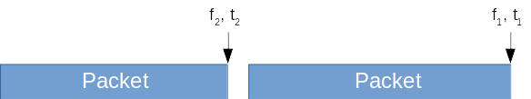
Transmission Scheduling
Transmission queuing and execution is managed through BULK IO's timestamp. Providing a timestamp of 0 or in the past results in immediate transmission. Providing a timestamp in the future queues the packet for transmission when the current time matches the timestamp. This packet transmission process is shown below:

std::string stream_id = "testStream";
unsigned int size_packet_1 = 1000;
unsigned int size_packet_2 = 500;
unsigned int size_packet_3 = 400;
double t1 = 5;
double t2 = t1+5;
double t3 = t2+4;

BULKIO::PrecisionUTCTime tstamp = bulkio::time::utils::now();
double twsec = tstamp.twsec;

bulkio::OutShortStream outputStream = dataShort_out->getStream(stream_id);
if (!outputStream) {
    outputStream = dataShort_out->createStream(stream_id);
    outputStream.blocking(true);
}
redhawk::buffer<short> Packet1(size_packet_1);
// data would be added to Packet1 here
tstamp.twsec = twsec + t1;
outputStream.write(Packet1, tstamp);

redhawk::buffer<short> Packet2(size_packet_2);
// data would be added to Packet2 here
tstamp.twsec = twsec + t2;
outputStream.write(Packet2, tstamp);

redhawk::buffer<short> Packet3(size_packet_3);
// data would be added to Packet3 here
tstamp.twsec = twsec + t3;
outputStream.write(Packet3, tstamp);
As shown above, the different packets are queued through the port's stream API, with the provided timestamp giving the transmitter transmission directions.
Note that transmit queues are not supported in VITA49 or SDDS ports.
BULK IO is also used when transmissions are to be sent over different frequencies. The re-tuning instructions are inserted as keyword CHAN_RF in SRI updates, as seen below:
std::string stream_id = "testStream";
unsigned int size_packet_1 = 1000;
unsigned int size_packet_2 = 500;
double t1 = 5;
double t2 = t1+5;
double f1 = 1e6;
double f2 = 2e6;

BULKIO::PrecisionUTCTime tstamp = bulkio::time::utils::now();
double twsec = tstamp.twsec;

bulkio::OutShortStream outputStream = dataShort_out->getStream(stream_id);
if (!outputStream) {
    outputStream = dataShort_out->createStream(stream_id);
    outputStream.blocking(true);
}

redhawk::PropertyMap new_keywords;

new_keywords["CHAN_RF"] = f1;
outputStream.keywords(new_keywords);
redhawk::buffer<short> Packet1(size_packet_1);
// data would be added to Packet1 here
tstamp.twsec = twsec + t1;
outputStream.write(Packet1, tstamp);

new_keywords["CHAN_RF"] = f2;
outputStream.keywords(new_keywords);
redhawk::buffer<short> Packet2(size_packet_2);
// data would be added to Packet2 here
tstamp.twsec = twsec + t2;
outputStream.write(Packet2, tstamp);
Note that the stream id plays no role in the basic transmit API. Stream id differentiation becomes important when different transmission priorities are mixed. To provide a stream id a particular priority, add the keyword FRONTEND::PRIORITY with value of type short with the stream's priority to the SRI keywords.
std::string stream_id = "testStream";
unsigned int size_packet_1 = 1000;
unsigned int size_packet_2 = 500;
double t1 = 5;
double t2 = t1+5;
double f1 = 1e6;
double f2 = 2e6;
short priority = 3;

BULKIO::PrecisionUTCTime tstamp = bulkio::time::utils::now();
double twsec = tstamp.twsec;

bulkio::OutShortStream outputStream = dataShort_out->getStream(stream_id);
if (!outputStream) {
    outputStream = dataShort_out->createStream(stream_id);
    outputStream.blocking(true);
}

redhawk::PropertyMap new_keywords;

new_keywords["CHAN_RF"] = f1;
new_keywords["FRONTEND::PRIORITY"] = priority;
outputStream.keywords(new_keywords);
redhawk::buffer<short> Packet1(size_packet_1);
// data would be added to Packet1 here
tstamp.twsec = twsec + t1;
outputStream.write(Packet1, tstamp);

new_keywords["CHAN_RF"] = f2;
// note that new_keywords still contains FRONTEND::PRIORITY
outputStream.keywords(new_keywords);
redhawk::buffer<short> Packet2(size_packet_2);
// data would be added to Packet2 here
tstamp.twsec = twsec + t2;
outputStream.write(Packet2, tstamp);
When overlapping scheduled transmissions conflict, the transmission with the higher priority is transmitted.
Implicit Continuous burst
To transmit multiple packets as a single continuous signal burst, setting the timestamp to immediately follow end of the last symbol can lead to undefined boundary conditions.
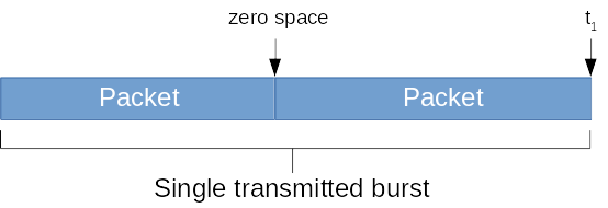
To remove the ambiguity of the transmitted construct, the timestamp in subsequent packet(s) can be set such that the separate packets are interpreted by the transmitter as a continuous transmitted signal. To do so, set the timestamp to invalid and both the whole (twsec) and fractional (tfsec) to 0, as shown below:
std::string stream_id = "testStream";
unsigned int size_packet_1 = 1000;
unsigned int size_packet_2 = 500;

BULKIO::PrecisionUTCTime tstamp = bulkio::time::utils::now();

bulkio::OutShortStream outputStream = dataShort_out->getStream(stream_id);
if (!outputStream) {
    outputStream = dataShort_out->createStream(stream_id);
    outputStream.blocking(true);
}

redhawk::buffer<short> Burst1(size_packet_1);
// data would be added to Burst1 here
tstamp.twsec = tstamp.twsec + 5;
outputStream.write(Burst1, tstamp);

redhawk::buffer<short> Burst2(size_packet_2);
// data would be added to Burst2 here
tstamp.tcstatus = BULKIO::TCS_INVALID;
tstamp.tfsec = 0;
tstamp.twsec = 0;
outputStream.write(Burst2, tstamp);
Explicit Continuous burst
There are instances when the concern exists that data might be lost without any feedback. This error can occur when data is received over UDP multicast rather than point-to-point Bulk IO. In such cases, a burst needs to be defined as continuous explicitly rather than implicitly. To declare a stream as continuous, used the keyword FRONTEND::CONTINUOUS_STREAM with the boolean True as its value in the SRI. Adding FRONTEND::CONTINUOUS_STREAM sets the transmitter to ignore all timestamps except for the first one.
The first timestamp provides a start cue. Subsequent timestamps are ignored. If any gaps appear on the stream, where data is not available when it is needed, a DEV_UNDERFLOW is triggered.
Transmit Arrays
Much like receivers, transmitters can be associated as arrays. The association of coherent devices is performed with the TX_ARRAY device. Much like RX_ARRAY, allocations of coherent transmit channels is by providing TX_ARRAY with the allocation property FRONTEND::coherent_feeds.
Calling allocate() on the TX_ARRAY device with FRONTEND::coherent_feeds is a sequence of the TDC devices that satisfied the request.
Feedback
Feedback from the device is sent through the TDC's status port, as seen in the following figure:
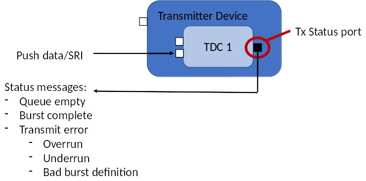
The TDC's status port is named "transmitDeviceStatus_out" and uses the TransmitDeviceStatus interface. The DeviceStatus interfaces is as follows:
module CF {
    enum DeviceStatusCodeType {
        DEV_OK,                             // device operating normally
        DEV_UNDERFLOW,                      // not enough data to fill the needed time
        DEV_OVERFLOW,                       // hardware cannot transmit the data at the rate requested
        DEV_INSUFFICIENT_SETTLING_TIME,     // time difference between end of last transmit and new transmit with a tune is insufficient
        DEV_MISSED_TRANSMIT_WINDOW,         // transmit could not begin at the requested time
        DEV_INVALID_TRANSMIT_TIME_OVERLAP,  // the timestamp for the last sample in the previous packet is after the timestamp for the first sample in the current packet
        DEV_INVALID_HARDWARE_STATE,         // hardware state is invalid (e.g.: configuration placed hardware in an invalid state)
        DEV_HARDWARE_FAILURE                // general hardware failure
    };

    // generic device status
    struct DeviceStatusType {
        string                      device_id;      // unique device instance id
        string                      allocation_id;
        CF::UTCTime                 timestamp;
        CF::DeviceStatusCodeType    status;         // device status
        string                      message;        // status-specific message
        CF::Properties              props;          // status-specific properties
    };

    interface DeviceStatus {
        // triggers for status message: change in status
        void statusChanged(in DeviceStatusType status);
    };
};

module FRONTEND {
    struct TransmitStatusType {
        string                      stream_id;
        string                      allocation_id;
        CF::UTCTime                 timestamp;
        unsigned long long          total_samples;  // number of samples transmitted from this stream id; resets to 0 when >= max Ulonglong
        unsigned long long          total_packets;  // number of packets transmitted (pushPacket calls) from this stream id; resets to 0 when >= max Ulonglong
        boolean                     transmitting;   // true when currently transmitting, false when no queued data to transmit
        CF::DeviceStatusCodeType    status;         // device status
        double                      settling_time;  // this is the hardware's current re-tune settling time
        unsigned long               queued_packets; // number of packets that are yet to be transmitted (current queue size)
    };

    interface TransmitDeviceStatus : CF::DeviceStatus {
        // triggers for status message: change in status, change in transmitting, or queued_packets increases or becomes zero
        void transmitStatusChanged(in TransmitStatusType status);
    };
};
Control of the transmitter, beyond that afforded by timestamps and keywords in BULK IO, is concerned with error recovery. For example, in some CONOPs it may be required to have a well-defined strict schedule of transmitted packets, while in other CONOPs, it may be acceptable for some packets to be sent with loose timing or not at all. The response to error states is defined by the TransmitControl interface, which in turn inherits from the DigitalTuner interface:
interface TransmitControl : DigitalTuner {
    struct TransmitParameters {
        string  stream_id;          // if empty string, then applies to all streams
        boolean ignore_timestamp;   // set to true for continuous data. Insufficient data will cause an DEV_UNDERFLOW error
        boolean ignore_error;       // set to true to ignore error states and just transmit
        double  tx_power;           // -1 for don't care
        double  max_timing_error;   // how much deviation (over/under) before DEV_MISSED_TRANSMIT_WINDOW is set as the error code; -1 for don't care
        // time for the packet transmission is the bulk io timestamp, unless ignore_timestamp is true; then data is sent as soon as it is available
        // center frequency for the packet transmission is CHAN_RF keyword in SRI
        // duration of the packet is the length of the packet * the sampling period (in SRI)
    };

    // reset allocation(s):
    //    - remove error codes
    //    - empty the transmit queue
    //    - reset total_samples count
    //    - reset total_packets count
    // if stream_id == "", the reset applies to all streams
    void reset(in string stream_id)
        raises (FRONTEND::FrontendException);

    // do not transmit the given stream id
    // queue the transmission until the stream id is allowed again
    //  return false if the stream id does not exist
    //  return true if the stream id exists
    boolean hold(in string stream_id)
        raises (FRONTEND::FrontendException);

    // list the stream ids that are currently in a "hold" state
    CF::StringSequence held()
        raises (FRONTEND::FrontendException);

    // allow the given stream id to transmit
    // if the transmission is queued, immediately transmit if timestamp is zero or set to ignore
    //  return false if the stream id does not exist
    //  return true if the stream id exists
    boolean allow(in string stream_id)
        raises (FRONTEND::FrontendException);

    void setTransmitParameters(in TransmitParameters transmit_parameters)
        raises (FRONTEND::FrontendException, FRONTEND::BadParameterException);

    TransmitParameters getTransmitParameters()
        raises (FRONTEND::FrontendException);
};
Note that the allocation id is not an argument for these function calls. Since each TDC is associated with a single allocation, a call over the TDC's TransmitControl interface is implicitly associated with the allocation. Calls to a device over the TransmitControl interface apply to all children of the devices that support the TransmitControl interface.
The reset method of the TransmitControl interface allows a device to exit the error state, empty its transmit queue, and reset all transmission counters. Set ignore_error to true in the TransmitParameters for the device's best-effort attempt to transmit data irrespective of error state. If ignore_error is set to true and an error condition occurs, such as an DEV_OVERFLOW, the device will notify the error state but continue to transmit.
Quick Response
In cases where a response to a particular event is required quickly, it may not be feasible to build the transmission (multiple pushPacket and pushSRI) in the time allowed. For these cases, the transmit API allows the creation of a response and queue it in the device. When the time to transmit is identified, a single call can be used to trigger the event.
To build a transmit queue, use the hold() method to hold a particular stream id. The return value of the hold method is a boolean describing whether or not the transmitter is aware that the stream id exists. A return value of false means that the device has yet to see the stream id. Irrespective of the return value, any arriving data associated with this stream id is queued.
To trigger a transmission, call allow() with the argument set to the selected stream id. The transmit queue for this stream is emptied as described in the following list:
- If the transmitter is set with ignore_timestamp as true:
The data will be transmitted as soon allow() is invoked for that stream id.
- The timestamps can be zero or non-zero. Either way the packets are transmitted as soon as the stream is allowed to transmit.
- If the transmitter is set with ignore_timestamp as false:
- If the initial packet timestamp is non-zero and the value is in the past, the error DEV_MISSED_TRANSMIT_WINDOW is triggered.
- If the initial packet timestamp is in the future, the data will be transmitted when the current time is equal to the timestamp.
If the initial packet timestamp tfsec and twsec are set to zero, then the first packet immediately transmits.
- If subsequent packets have tfsec=twsec=0, they are transmitted in the order in which they were received without delay between packets.
- Delays may occur if the transmitter needs to pause because of events like changing the transmit frequency or transmit bandwidth
- If subsequent packets have non-zero tfsec or twsec, the timestamp value is how long each of these subsequent packets need to be delayed with respect to the initial transmitted packet.
To retrieve the list of streams that are on hold, call the held() method.
Error States
There are multiple errors associated with the FEI transmit API.
DEV_UNDERFLOW
The transmitter sets its transmission rate based on the xdelta (sampling period) for the stream. DEV_UNDERFLOW occurs when ignore_timestamp is set to true and there is not enough queued data to maintain the requested transmit rate.
DEV_OVERFLOW
The given xdelta (sampling period) for the stream indicates a sample rate that is higher than the maximum rate supported by the transmitter. If ignore_error is true, data is transmitted at the maximum rate supported by the hardware.
DEV_INSUFFICIENT_SETTLING_TIME
The time difference between packets where a re-tune occurred is insufficient for the transmitter to settle to the new frequency before the provided timestamp expires. This error cannot occur if ignore_timestamp is set to true.
DEV_MISSED_TRANSMIT_WINDOW
The data packet was received too late to honor the timestamp. This error cannot occur if ignore_timestamp is true.
DEV_INVALID_TRANSMIT_TIME_OVERLAP
The difference in timestamp between consecutive packets is less than the length of the first packet. This error cannot occur if ignore_timestamp is true.
DEV_INVALID_HARDWARE_STATE
The hardware has been incorrectly configured. The hardware cannot function as configured and the device is no longer transmitting irrespective of the state of the ignore_error flag.
DEV_HARDWARE_FAILURE
A catastrophic hardware failure has been detected. The hardware can no longer function and the device is no longer transmitting irrespective of the state of the ignore_error flag.
Conflicting transmit stream scenarios
The following sections describe several scenarios (and the resulting behavior) where the timestamp and priority between different streams conflict.
Transmission with Multiple Priorities and Not Ignore Errors
Transmission with mixed priorities will lead to mixed error conditions. Suppose the transmitter is currently supporting transmissions for "Stream A" with no set priority. The transmissions for "Stream A" are queued and are in the process of transmission. A new stream, "Stream B", is received by the TDC. "Stream B" has FRONTEND::PRIORITY = 5, and transmissions that overlap with "Stream A" packets. Assuming that stream_id = "", ignore_error = false, and ignore_timestamp = false in TransmitParameters, the following occurs:
- "Stream B" packets are transmitted
- "Stream A" queued packets are flushed
- A TransmitStatusType status change is generated:
- stream_id = "Stream A"
- status = DEV_INVALID_TRANSMIT_TIME_OVERLAP
- All subsequent received "Stream A" packets are immediately flushed
- "Stream B" packets proceed as planned and as they arrive
- If new "Stream C" with no priority set arrives, this stream operates normally until it overlaps with "Stream B"
Transmission with Multiple Priorities and Ignore Errors
Transmission with mixed priorities will lead to mixed error conditions. Suppose the transmitter is currently supporting transmissions for "Stream A" with no set priority. The transmissions for "Stream A" are queued and are in the process of transmission. A new stream, "Stream B", is received by the TDC. "Stream B" has FRONTEND::PRIORITY = 5, and has transmissions that overlap with "Stream A" packets. Assuming that stream_id = "", ignore_error = true, and ignore_timestamp = false in TransmitParameters, the following occurs:
- "Stream B" packets are transmitted
- "Stream A" packets that overlap with "Stream B" packets are flushed
- A TransmitStatusType status change is generated:
- stream_id = "Stream A"
- status = DEV_INVALID_TRANSMIT_TIME_OVERLAP
- All subsequent received "Stream A" packets are flushed if they overlap with "Stream B" packets
- "Stream B" packets proceed as planned and as they arrive
- If new "Stream C" with no priority set arrives, this stream operates normally until it overlaps with "Stream B" or "Stream A"
Transmission with Multiple Priorities and Ignore Timestamp (both values of Ignore Errors)
Transmission with mixed priorities will lead to mixed error conditions. Suppose the transmitter is currently supporting transmissions for "Stream A" with no set priority. The transmissions for "Stream A" are queued and are in the process of transmission. A new stream, "Stream B", is received by the TDC. "Stream B" has FRONTEND::PRIORITY = 5, and has transmissions that overlap with "Stream A" packets. Assuming that stream_id = "", ignore_error = false, and ignore_timestamp = true in TransmitParameters, the following occurs:
- "Stream B" packets are transmitted
- "Stream A" queued packets are ignored until "Stream B" queue is empty
- "Stream B" packets proceed as planned and as they arrive; the "Stream A" packet queue is ignored until the "Stream B" packet queue is empty
- If new "Stream C" with no priority set arrives, this stream queue is ignored until "Stream B" queue is empty
- "Stream C" amd "Stream A" queues are handled on a first-come-first-served basis
Because no error condition was triggered, the value of ignore_error has no effect on this scenario.
Transmission with Equal (or no) Priorities and Not Ignore Errors
Transmission with equal priorities or priorities not set will lead to consistent error conditions. Suppose the transmitter is currently supporting transmissions for "Stream A" with no set priority. The transmissions for "Stream A" are queued and are in the process of transmission. A new stream, "Stream B", is received by the TDC also with no set priority. "Stream B" has transmissions that overlap with "Stream A" packets. Assuming that stream_id = "", ignore_error = false, and ignore_timestamp = false in TransmitParameters, the following occurs:
- "Stream A" queued packets are flushed
- "Stream B" queued packets are flushed
- TransmitStatusType status change is generated:
- stream_id = "Stream A"
- status = DEV_INVALID_TRANSMIT_TIME_OVERLAP
- TransmitStatusType status change is generated:
- stream_id = "Stream B"
- status = DEV_INVALID_TRANSMIT_TIME_OVERLAP
- All subsequent received "Stream A" or "Stream B" packets are immediately flushed
- If new "Stream C" arrives, this stream is treated normally, since it will not overlap with the flushed packets
Transmission with Equal (or no) Priorities and Ignore Errors
Transmission with equal priorities or priorities not set will lead to consistent error conditions. Suppose the transmitter is currently supporting transmissions for "Stream A" with no set priority. The transmissions for "Stream A" are queued and are in the process of transmission. A new stream, "Stream B", is received by the TDC also with no set priority. "Stream B" has transmissions that overlap with "Stream A" packets. Assuming that stream_id = "", ignore_error = true, and ignore_timestamp = false in TransmitParameters, the following occurs:
- "Stream B" packets whose timestamp arrive while "Stream A" is transmitting are flushed
- "Stream A" packets whose timestamp arrive while "Stream B" is transmitting are flushed
- TransmitStatusType status change is generated:
- stream_id = "Stream A"
- status = DEV_INVALID_TRANSMIT_TIME_OVERLAP
- TransmitStatusType status change is generated:
- stream_id = "Stream B"
- status = DEV_INVALID_TRANSMIT_TIME_OVERLAP
- Subsequent "Stream A" and "Stream B" packets are handled on a first-come-first-served basis
- If new "Stream C" arrives also with no priority, this stream is treated equally to "Stream A" and "Stream B"
Error Recovery
To remove the error state from any one stream, reset() must be invoked on the TDC's control port. After reset() is invoked, any stream in an error state (e.g.: "Stream A" in the above examples), has the following event issued:
- TransmitStatusType status change is generated:
- stream_id = "Stream A"
- status = DEV_OK