Waveform Deployment and Computing Resources
Components are processes that run on a computer. As such, each component takes up some arbitrary, often time-varying amount of spare capacity (for example, CPU computing load, memory, network I/O). REDHAWK manages computing resources on every computer under its domain to minimize the likelihood that computing resources are over-subscribed. Each computer under REDHAWK’s domain is managed through the GPP process.
GPP Device
The GPP device is a specialized REDHAWK device that manages the deployment of components onto the computer and can be inspected like any other REDHAWK device.
GPP can be in three possible usage states: IDLE, ACTIVE, or BUSY.
IDLEindicates the GPP is not running any REDHAWK components.ACTIVEindicates the GPP is running at least one component, but has spare capacity to run additional components.BUSYindicates the GPP does not have any spare capacity to run additional components.
The usage state of any device can be accessed through its usageState member. To inspect the usage state:
- In the IDE, select the “Advanced” tab of the “Properties” tab for the deployed device.
In a Python session, run the following script (assuming a domain is running):
>>> from ossie.utils import redhawk
>>> dom=redhawk.attach()
>>> dev = dom.devMgrs[0].devs[0]
>>> print dev._get_usageState()
The GPP contains several properties that are critical for the deployment of components to a device. When a waveform is deployed, the framework scans through all IDLE and ACTIVE GPP devices. The component’s os and/or processor elements from its Software Package Descriptor (SPD) file are compared against the GPP’s os_name and/or processor_name properties, respectively. If there is a match, the component is assigned to that GPP. This search/assignment is performed for all components in the waveform. Once all components have been assigned to specific GPPs, the deployment process begins.
Deployment Process
The deployment of a component to a GPP begins by copying all relevant files from $SDRROOT/dom/components/<component>/ to the GPP’s cache. The GPP cache is a temporary directory on the computer used to run each component (recall that REDHAWK is designed to support distributed processing). The cache is located in the local computer’s $SDRROOT/dev/.<Device Manager name>/<Device Name>. Note that the component’s working directory is the GPP’s cache directory.
After all files are copied, the component is started in its own process space using the fork system call. At program startup, the component registers with the Domain Manager and the initial property state is applied to the component’s property values. Next, connections are created as defined in the waveform file. The waveform is successfully deployed when all waveform components are registered with the Domain Manager and all component initialization is complete.
Shared Address Space Components
Shared address space components (C++ only) are deployed differently than executable components. The component files are still copied, but an additional specialized component called ComponentHost is deployed to the GPP to manage the components. The GPP only executes the ComponentHost via fork and exec. Once the ComponentHost registers with the Domain Manager, all of the shared address space components assigned to the GPP are executed in the ComponentHost. The remainder of the deployment process is the same as for executable components.
Using Valgrind to Debug Components
The GPP supports launching components using Valgrind, an open source tool that helps detect memory errors and leaks.
The VALGRIND environment variable controls this behavior:
- If
VALGRINDis not set, components launch as usual. - If
VALGRINDis set but has no value, the GPP searches the path forvalgrind. - If
VALGRINDhas a value, it is assumed to be the full path to thevalgrindexecutable.
Valgrind log files are written to the same directory as the component entry point within the GPP’s cache. For example, if the component, MyComponent, has an entry point of cpp/MyComponent, the logs are written to MyComponent/cpp. The log file name follows the pattern valgrind.<PID>.log, where PID is the process ID of the component.
Monitoring Computing Resources per Application
Each application object has a metrics function that provides access to application-level metrics. The available metrics include:
cores: number of cores usedmemory: amount of memory occupiedprocesses: how many processes make up the componentfiles: how many file handles the component has openthreads: how many threads the component has openshared: whether or not it is a shared address space component (C++ only)componenthost: The ID for the component’s host- Component ID for C++ components generated in RH 2.0 or earlier, and Python and Java components
ComponentHost_GPP_1for shared address space C++ components
The metrics are available on a per-component basis or aggregated for the whole application.
The metrics function takes two arguments, the list of components to report and the metrics to report, where the ID “application utilization” is used to retrieve the application’s aggregated metrics. Both arguments to the metrics function are lists of strings. To retrieve all metrics for all components as well as the aggregated application, use empty lists for both arguments.
To display metrics in the IDE, select a running waveform, and in the Properties view, select the Metrics tab.
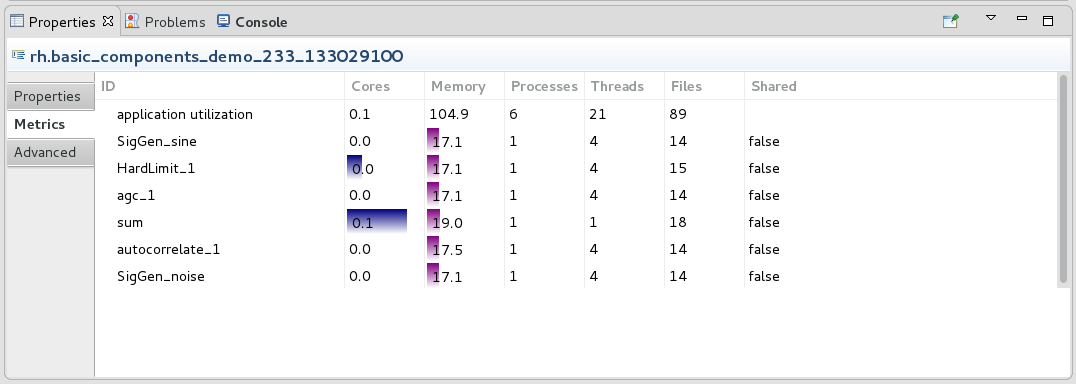
Waveform Metrics
Monitoring Computing Resources per GPP
The GPP monitors the following resources:
- System: CPU utilization, memory usage, nic usage, total number of threads, and number of open files
- For each component: CPU usage, memory usage, and process state
When a component fails (for example, segfault), the GPP issues a AbnormalComponentTerminationEventType message on the IDM_Channel. The message contains the component ID of the component that failed, the application ID for the component’s waveform, and the device ID for the GPP that is running the component.
The GPP contains a thresholds structure with five elements. If at any point any of these thresholds is exceeded (because of any process’s usage, not just those forked by the GPP), the GPP usage state changes to BUSY.
The following table describes the elements of the thresholds structured property:
Thresholds Structured Property
| Element | Description |
|---|---|
mem_free |
Amount of free memory available that triggers a threshold condition (default units in MB). |
nic_usage |
Amount of network capacity used by the NIC interface that triggers a threshold condition. |
threads |
Percentage of threads available to the GPP that triggers a threshold condition. |
files_available |
Percentage of file handles remaining to the GPP that triggers a threshold condition. |
cpu_idle |
Amount of CPU idle percentage that triggers a threshold condition. |
ignore |
Ignore all thresholds and never enter into a BUSY state. |
To disable the GPP’s response to any threshold, set thresholds.ignore to True. If thresholds.ignore is True, the GPP will either be in an IDLE state if no components are deployed, or an ACTIVE state if one or more component is deployed, but never BUSY, irresepecitve of the overall computer usage.
Setting any element of the thresholds structure to -1 disables the GPP’s response to that particular element.
For example, to ignore the processor’s usage, set thresholds.cpu_idle to -1. The GPP state will be IDLE if no components are deployed, and ACTIVE if one or more component is deployed, irrespective of the cpu idle percentage.
Setting any element of the thresholds structure to 0 changes the GPP usage state to BUSY, and thus, the GPP cannot launch any addtional components.
The GPP contains a utilization structured property that shows the overall system utilization at any time. The following table describes the elements of the utilization structured property.
Utilization Structured Property
| Element | Description |
|---|---|
description |
Human-readable description of the content. In the case of CPU usage, this element’s content is “CPU cores”. The numbers in this structure reflect the effective number of cores that are being utilized. |
component_load |
Overall load by all the components that were forked by the GPP. |
system_load |
Total load from every process, irrespective of whether or not it was forked by this GPP. |
subscribed |
Sum of the total system load and however much is reserved. (Refer to Capacity Reservation). |
maximum |
Maximum load that the GPP will accept before switching to a BUSY state. |
ComponentHost
ComponentHost is a specialized REDHAWK component that launches and manages shared address space components in a waveform. It is installed in $SDRROOT on the DomainManager and deployed to the GPP as required. There is no need to explicitly include ComponentHost in a Software Assembly Descriptor (SAD) file, as the Application Factory automatically creates one (or more) as part of the waveform deployment.
One ComponentHost instance is created per GPP, per waveform; all shared address space components assigned to the same GPP in a waveform reside within the same ComponentHost. Within ComponentHost, each started component runs as a separate thread, named according to the component’s label. The individual component’s main threads may be viewed in common Linux utilities such as top by enabling the display of threads. Other threads, such as those used for I/O by the middleware layer, are typically named according to the ComponentHost instance.
Binding Components to Executable Devices
For standard application/component deployment, the Application Factory searches the domain to find a matching executable device using the OS and architecture implementation properties and optional implementation dependencies. The first available executable device matching those properties is selected as the deployment device for the component. The SAD and Device Configuration Definition (DCD) files now allow system integrators to define additional id/value pairs to match against when deploying a component to an executable device. The following example describes the new xml elements (devicerequires and deployerrequires), that allow Component_1 to be deployed only on RED_NODE:GPP_1.
<!-- example of ID/value pairs for a component in a SAD file
<componentplacement>
  <componentfileref refid="Component_SPD_1"/>
  <componentinstantiation id="Component_1" startorder="0">
    <usagename>Component_1</usagename>
    <findcomponent>
      <namingservice name="Component_1"/>
    </findcomponent>
    <devicerequires>
        <simpleref refid="color" value="RED"/>
        <simpleref refid="rank" value="15"/>
    </devicerequires>
  </componentinstantiation>
</componentplacement>
<!-- example of ID/value pairs for a GPP in a DCD file
<componentplacement>
<componentfileref refid="GPP1_SPD_1"/>
<componentinstantiation id="RED_NODE:GPP_1">
<usagename>RED_NODE:GPP_1</usagename>
<deployerrequires>
<requires id="color" value="RED"/>
<requires id="rank" value="15"/>
</deployerrequires>
</componentinstantiation>
</componentplacement>During the deployment process, when a component has a devicerequires id/value set defined in a SAD file, the list of available executable devices in the domain is filtered based on the entire id/value set. The Application Factory performs a match against the devicerequires id/value pairs and the executable devices’s devicerequires id/value pairs. If there is an exact match between both sets, that executable device is selected as the deployment device. If no matching executable devices are found, then the waveform fails to deploy and an exception is raised.
In addition to allowing components to select deployment devices, an executable device with a devicerequires id/value set restricts deployment to only components with a matching id/value set. All other requests for deployment to that executable device fail.
For host collocation and regular deployment requests, the following table explains the deployment behavior for devicerequires and deployerrequires id/value sets:
Deployment Matching
| device requires | deployer requires | Host Collocation | Match | Deployment |
|---|---|---|---|---|
| Yes | Yes | No | Yes | Yes, deploy on matching device. |
| Yes | Yes | No | No | No, matching failed. |
| Yes | No | No | No | No, device not used for deployment. |
| No | Yes | No | No | No, skip this device. |
| Yes (single set) | Yes | Yes | Yes | Yes, entire host collocation on this device. |
| Yes (mixed sets) | Yes | Yes | Yes | No, different devicerequire sets will fail. |
| Yes (same sets) | Yes | Yes | Yes | Yes, entire host collocation on this device. |
| No | Yes | Yes | Yes | No, skip this device. |
Capacity Reservation
A non-reservation strategy assumes that each process is running at full capacity at the time of execution. This is clearly not the case when the waveform is initially deployed because all of the waveform’s components are in a stopped state, thus taking little to no system resources. Only after the waveform is switched to a started state do the components begin to consume system resources. Those system resources that are monitored for threshold changes by the GPP will directly affect the Device’s usageState: IDLE, ACTIVE, or BUSY.
A non-reservation strategy with a deployment pattern where multiple waveforms are launched and not initially started but are delayed due to system events or predefined behavior, can create an over-utilized system. For example, a system may initially create twenty instances of a waveform and later, start them as a result of an aperiodic event. All twenty waveforms are created, but starting the 15th instance causes the CPU utilization for the entire system to reach 100%. When the next five waveforms are started, the system will be over utilized, and all running components will be affected leading to degraded system performance, such as data loss or lack of timely response to message events.
To mitigate this issue, the GPP maintains a reservation-based strategy to properly forecast the CPU load for each component it manages. During initial waveform deployment, the forecasted load for each component of the waveform is reserved against the current system’s available CPU capacity. As components are moved to the start state, the forecasted load is tabled, and the actual load or a minimum utilitization load (whichever is greater), is used for determining the system load, and thus, the available CPU capacity. The available CPU capacity is one of the system resources that will directly determine the system’s usageState, (i.e., IDLE, ACTIVE, or BUSY ). The GPP’s utilization.subscribed property maintains the runtime value of the total reservation for the system.
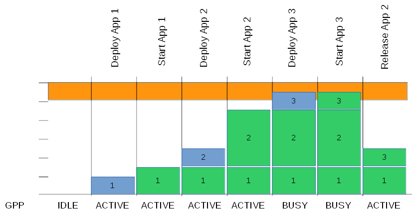
Example Reservation Schema
In the figure above, an example of the reservation schema is shown where actual usage is shown in green, reserved capacity is shown in blue, and the maximum for the host is shown in orange. In the figure shown, the GPP’s capacity calculation is affected by the components deployed and whether or not its host application is started.
The property, reserved_capacity_per_component, is the default forecasted load for every component deployed by the GPP.
Specialized Reservation
The generalized reservation schema based on a common value set for all components is functional but often too generic. Furthermore, as the load imposed by a component changes (for example, as the noise environment changes), a floor for the component’s load is needed. For such a case, a per-component load floor can be set. This floor is maintained when the component’s load is lower than the specified value. However, the component’s load is computed as the actual load when it exceeds the floor value set. In other words, the component’s effective load is the higher of the floor or actual load. Currently, this floor is only available through the REDHAWK Python package when the waveform is created. The following example describes how to set the reserved forecasted load for a component. In this example, the component, my_comp_1, on the waveform, my_wave, has a reservation floor of 4 cpu cores.
from ossie.utils import redhawk
from ossie.cf import CF
from omniORB import any, CORBA
dom=redhawk.attach()
dev = dom.devMgrs[0].devs[0]
extra_reservation = 4  # number of cores to reserve/utilize
_value=any.to_any(extra_reservation)
_value._t=CORBA.TC_double  # make sure that the number is packed as a double
app_1=dom.createApplication('/waveforms/my_wave/my_wave.sad.xml','my_wave',[CF.DataType(id='SPECIALIZED_CPU_RESERVATION',value=any.to_any([CF.DataType(id='my_comp_1',value=_value)]))])
print dev._get_usageState()  # view the reservation effect
In other cases, an aggregate load for a whole waveform is needed rather than loads for individual components. To support this need, it is possible to provide a reservation floor on a per-host collocation basis rather than on a per-component basis. The reservation floor can be set through the SAD file or as a waveform creation parameter.
When the reservation is based on the SAD file, it is added through an additional child element to the hostcollocation element. The additional child element is reservation, with two attributes: kind (“cpucores” for processing) and value (in this case, the number of cores that should be reserved). For example, if a host collocation were to include a reservation for a hostcollocation with component “some_comp” and an aggregate reservation of 3 cores, it would follow a pattern similar to this:
<hostcollocation id="ID_TEST_SET1" name="COLLOC_SET1">
  <componentplacement>
    <componentfileref refid="some_comp_ref"/>
    <componentinstantiation id="SigGen_1" startorder="0">
      <usagename>SigGen_1</usagename>
      <findcomponent>
        <namingservice name="SigGen_1"/>
      </findcomponent>
    </componentinstantiation>
  </componentplacement>
  <reservation kind="cpucores" value="3"/>
</hostcollocation>
Alternatively, the reservation can be made in the IDE by selecting a host collocation in the SAD editor diagram and editing the reservation in the Properties view. The following procedure explains how to set the reservation using the IDE.
- Create a new Waveform project.
- In the SAD diagram, add a host collocation.
- Edit the host collocation’s name to match the XML (
COLLOC_SET1). - Add
rh.SigGento the host collocation. - Select the host collocation.
- Open the Properties view, select the Reservations tab.
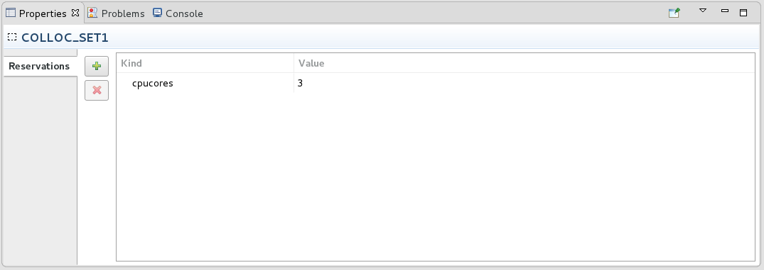
Properties View Reservations Tab
- Click the + button.
- Set the Kind and Value to match the XML (
cpucoresand3, respectively).
When a waveform contains a single host collocation, it is possible to provide an override value for that host collocation by providing an empty ID to the SPECIALIZED_CPU_RESERVATION.
from ossie.utils import redhawk
from ossie.cf import CF
from omniORB import any, CORBA
dom=redhawk.attach()
dev = dom.devMgrs[0].devs[0]
extra_reservation = 4  # number of cores to reserve/utilize for the host collocation
_value=any.to_any(extra_reservation)
_value._t=CORBA.TC_double  # make sure that the number is packed as a double
app_1=dom.createApplication('/waveforms/my_wave/my_wave.sad.xml','my_wave',[CF.DataType(id='SPECIALIZED_CPU_RESERVATION',value=any.to_any([CF.DataType(id='',value=_value)]))])
print dev._get_usageState()  # view the reservation effect
If the waveform contains more than one host collocation, it can be overloaded through the host collocation’s id. For example, if the SAD example above were to be overloaded with 4 cores rather than 3, the code would look as follows:
from ossie.utils import redhawk
from ossie.cf import CF
from omniORB import any, CORBA
dom=redhawk.attach()
dev = dom.devMgrs[0].devs[0]
extra_reservation = 4  # number of cores to reserve/utilize for the host collocation
_value=any.to_any(extra_reservation)
_value._t=CORBA.TC_double  # make sure that the number is packed as a double
app_1=dom.createApplication('/waveforms/my_wave/my_wave.sad.xml','my_wave',[CF.DataType(id='SPECIALIZED_CPU_RESERVATION',value=any.to_any([CF.DataType(id='ID_TEST_SET1',value=_value)]))])
print dev._get_usageState()  # view the reservation effect
Resource Affinity
Modern Linux kernels support the ability to define memory and processor affinity using the NUMA library. REDHAWK has added support to define processor affinity during the component deployment process as specified in a waveform’s SAD file. The affinity element can be added to the componentplacement/componentinstantiation element for the resource. During deployment, the REDHAWK GPP recognizes these options and performs the appropriate affinity requests when the resource is executed. An affinity request is defined by the following two intrinsic Property identifiers added to the affinity element.
affinity::exec_directive_class- The context classification of affinity directive to perform.affinity::exec_directive_value- Value to use when processing the affinity directive.
Affinity Class Directives
| Directive Class | Description | Values |
|---|---|---|
socket |
Processor affinity using a processor socket identifier set. | Supported values are defined by the NUMA library’s numa_parse_nodestring method; consult the NUMA man page for further clarification. |
cpu |
CPU affinity using a cpu identifier set. | Supported values are defined by NUMA library’s numa_parse_cpustring method; consult the NUMA man page for further clarification. |
nic |
Determine which CPU manages the nic’s interrupts then assign processor affiliation to that CPU. | Name of a host’s network interface. Processor identification is resolved by processing/proc/interrupts for the requested interface name. |
The current REDHAWK development tool set does not support the inclusion of the affinity element into a SAD file. Adding this element requires manual editing of the file with a text editor. The following example restricts the processor affinity for component C2_1 to CPU number 5.
<componentplacement>
  <componentfileref refid="C2_5fb7296e-b543-43fc-bc14-88a9299b458b"/>
  <componentinstantiation id="C2_1" startorder="1">
    <usagename>C2_1</usagename>
    <affinity>
      <simpleref refid="affinity::exec_directive_class" value="cpu" />
      <simpleref refid="affinity::exec_directive_value" value="5"/>
    </affinity>
    <findcomponent>
     <namingservice name="C2_1"/>
    </findcomponent>
  </componentinstantiation>
</componentplacement>