Using an FEI Device in the IDE
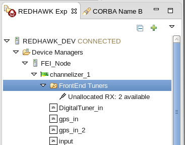
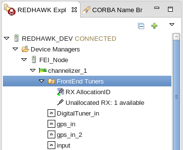
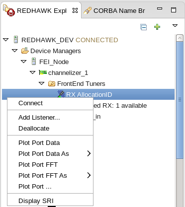
After you have created the FrontEnd Interfaces (FEI) device, you can launch the device in the sandbox or launch it in a domain as part of a node. For more information, refer to Launching Components in the IDE Sandbox or Creating a New Node and Launching a Domain. After launching the device, the FrontEnd Tuners folder is displayed under the device in the REDHAWK Explorer view and the available tuners are displayed under it with a tuning fork icon:
Allocating a FrontEnd Tuner
The usage status of a FrontEnd Tuner device is IDLE until a successful allocation has been made. Allocation is the process where a specific tuner is requested for use, and initial setup of the tuner is performed. When at least one channel has been allocated, but there is one channel not allocated, the device is ACTIVE. If all channels have been allocated, the device is BUSY.
The following procedure explains how to allocate a FrontEnd tuner using the Allocate Tuner wizard.
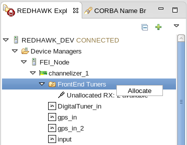
Right-click the FrontEnd Tuners folder and select Allocate:
The Allocate Tuner wizard is displayed. In this wizard, you specify the desired tuner properties such as frequency, bandwidth, and so forth.
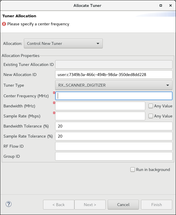
In the Allocation drop-down box, verify Control New Tuner is selected.
Optionally, in the New Allocation ID field, modify the text if needed.
In Tuner Type, select the appropriate tuner type. You have the following options:
- RX_DIGITIZER
- CHANNELIZER
- DDC
- RX
- RX_DIGITIZER_CHANNELIZER
- TX
- RX_SCANNER_DIGITIZER
For more information about tuner types, refer to Types of Tuners.
In Center Frequency (MHz), specify the center frequency.
NOTE
Bandwidth and sample rate must be specified during allocation. For an allocation to be successful, the tuner must be able to provide a value that is greater than or equal to the requested value without exceeding the appropriate tolerance value specified. Requesting a bandwidth or sample rate of zero (0.0) indicates to the tuner that any value is acceptable and that the tolerance values can be ignored. Requesting 0 typically results in the lowest value the tuner is capable of providing while still satisfying the remainder of the allocation request. If the Any Value checkbox is selected, a value of 0 is requested.
In Bandwidth (MHz), specify the bandwidth, or if a specific bandwidth is not required, select the Any Value checkbox.
In Sample Rate (Msps), specify the sample rate, or if a specific sample rate is not required, select the Any Value checkbox.
Optionally, adjust the Bandwidth Tolerance (%) or Sample Rate Tolerance (%) (Refer to Optional Status Elements).
Optionally, specify the ID of the analog feed in RF Flow ID or the device's Group ID.
If allocating a scanner, click Next. For any other allocation, click Finish.
For a scanner allocation, the Scanner Allocation page is displayed:
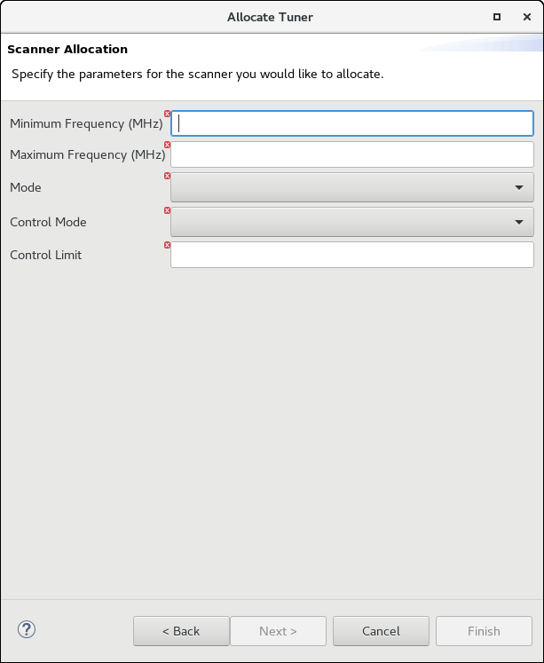
You must complete the following for the scanner:
In Minimum Frequency (MHz) and Maximum Frequency (MHz), specify the lower and upper bounds of the frequencies that will be scanned.
In Mode, select SPAN_SCAN to request scanning ranges of frequencies, or DISCRETE_SCAN to enumerate individual frequencies.
In Control Mode, select TIME_BASED to specify the minimum dwell time of the scanner in seconds, or SAMPLE_BASED to specify the minimum dwell time in samples.
In Control Limit, specify a lower bound on the dwell time.
Click Finish.
The tuner is allocated and is displayed under the FrontEnd Tuners folder with the truncated Allocation ID and an active tuning fork icon. If you left-click or hover over the allocated tuner, the full Allocation ID is displayed. A successful allocation tunes the hardware to the requested frequency and establishes a Bulk Input/Output (BulkIO) data stream containing the content. In the case of a multi-out BulkIO port, the data stream will only be pushed over a connection with a Connection ID that is identical to the Allocation ID associated with the data stream. In cases where the BulkIO port is not a multi-out port, all data streams are pushed over all connections, regardless of Connection ID.
Deallocating a Tuner
If a tuner was previously allocated, it can be deallocated. To deallocate a tuner, right-click the allocated FrontEnd tuner and select Deallocate. The tuner is deallocated and displays an inactive tuning fork icon along with a status of Unallocated.
Attaching a Listener to a Tuned Receiver
Sometimes, it is necessary for multiple different applications to share a single FEI source. To support this concept, FEI includes both allocation owners and listeners. The allocations that have been discussed so far are owners; they maintain complete control over the allocated hardware. Listeners, on the other hand, allow for an arbitrary number of applications to receive the same data that the allocation owner receives. However, listeners have no control over the source. Listener allocations can be made against a particular allocation (through the Allocation ID) or by parameters (i.e.: center frequency).
To allocate a listener, right-click the allocated FrontEnd tuner and select Add Listener. The Listener Allocation dialog is displayed: 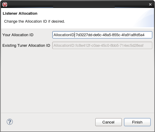
It is possible to specify an Allocation ID for the listener, but that is strictly optional (note that the listener Allocation ID is needed as the Connection ID when consuming the listener data). Click Finish to exit the wizard and allocate the listener. When the process is complete, the listener is associate with the receiver, and is displayed under the appropriate FrontEnd tuner.
Metadata from the Tuner Device
An FEI device provides metadata along with its data stream. This metadata is attached to the Signal Related Information's (SRI) keywords passed along BulkIO. A total of 5 SRI elements have been defined, and they are described below:
FEI Data Passed as SRI
| Identifier | Value | Type |
|---|---|---|
COL_RF |
The center frequency (in Hz) for the receiver that was used to receive the data. | double |
CHAN_RF |
The center frequency (in Hz) for the tuned receiver. | double |
FRONTEND::RF_FLOW_ID |
The identifier for the stream (usually the antenna), if available. | string |
FRONTEND::BANDWIDTH |
The bandwidth (in Hz) for the tuned signal. | double |
FRONTEND::DEVICE_ID |
The identifier for the device acquiring the data. | string |
Deallocating a Listener
If a listener was previously allocated, you can deallocate it. To deallocate a listener, right-click the allocated listener and select Deallocate.
Performing a Scan
After a tuner has been allocated in a scanning mode (RX_SCANNER_DIGITIZER), it can be given a scanning plan to execute.
Right-click the allocated FrontEnd tuner and select Scan. The Tuner Scan wizard is displayed:
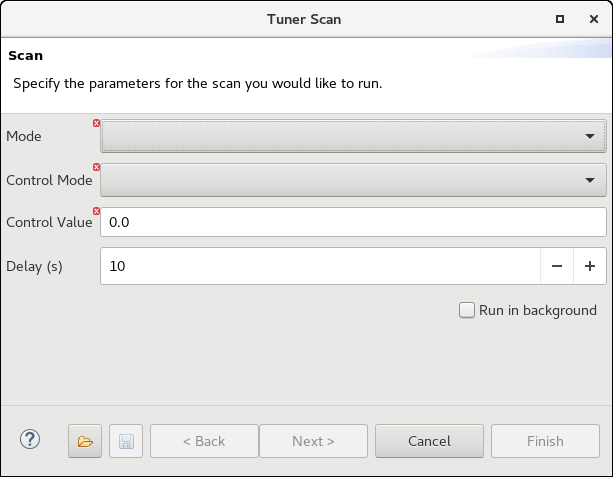
In Mode, select the type of scan to be performed. Use MANUAL_SCAN to specify a single frequency, DISCRETE_SCAN to provide a list of frequencies, or SPAN_SCAN to provide ranges of frequencies to step through.
In Control Mode, select TIME_BASED to specify the minimum dwell time of the scanner in seconds, or SAMPLE_BASED to specify the minimum dwell time in samples.
In Control Value, specify the dwell time.
In Delay (s), provide the number of seconds until the scan should start.
Click Next.
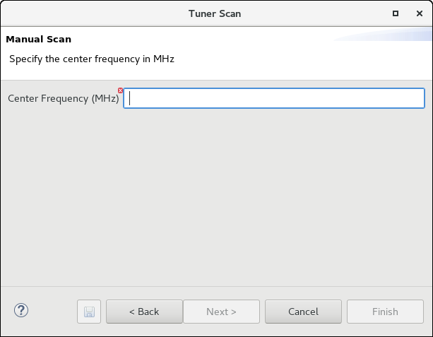
If MANUAL_SCAN was selected, the Manual Scan page is displayed and the single dwell frequency can be provided:
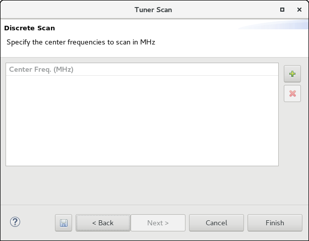
If DISCRETE_SCAN was selected, the Discrete Scan page is displayed and a list of frequencies can be provided:
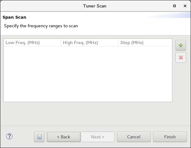
If SPAN_SCAN was selected, the Span Scan page is displayed and ranges of frequencies can be provided. Each range has a low (start) frequency, a high (ending) frequency, and the step width the scanner should use while scanning the range:
After entering the scan plan, click Finish. The scanning starts after the delay specified on the first page.
To save the data entered in the wizard to an XML file that can later be loaded, click the save button at the bottom of the wizard. To load a previously saved XML file, click the load button at the bottom of the wizard.
Controlling a Tuned Receiver
FEI devices can be controlled using a FrontEnd Tuner port. The port provides an interface to modify parameters such as center frequency, bandwidth, gain, and sample rate.
This tuner interface provides the ability to set parameters like center frequency and bandwith for the receiver. Any FEI compliant device may not output any data until the transients from any receiver setting change have settled to steady state. In short, all data output from an FEI compliant device must correspond to unambiguous receiver settings.
There is a custom view under each tuned receiver that sends commands over the control port. This custom view is mapped to the Properties view. Note that this is not a device property, but instead it is the use of the property view as the artifact for interacting with the port.
The following procedure explains how to control an allocated tuner.
Select the allocated tuner.
Select the properties tab if available. Otherwise, from the top IDE menu, select Window > Show View > Properties.
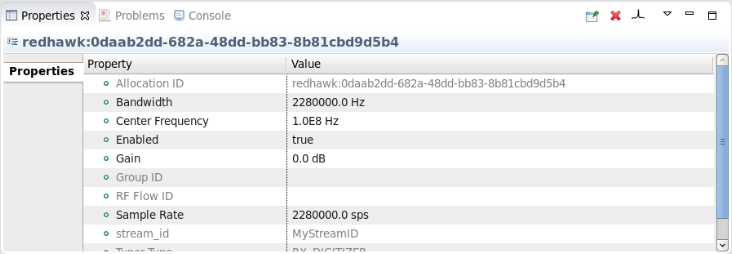
Select the entry, or entries, to change from this view.
Press Enter to have the change take affect or Esc to cancel.
Even though it is the property view, the Tuner port is exercised to effect the requested changes. If successful, the view updates and displays the new value.
Plotting a Tuned Receiver
The process described in Plotting BulkIO Ports only applies to a single-channel system. In multi-channel devices, a single port is used to send out all the data, so additional structures are used to identify which channel to plot.
To plot an FEI device, right-click the allocated FrontEnd tuner and select Plot Port Data, or any other Plot Port option:
If the FrontEnd tuner has multiple BulkIO ports, the Ambiguous Data Port dialog is displayed. Select the port to plot.
For more information about interacting with the plots, refer to REDHAWK Plot View.
Plotting a Tuned Receiver with Multiple Channels
In multi-channel devices, all data is pushed out of a single port. To disambiguate the traffic, additional structures are used. When a device or component contains both a BulkIO output port and the well-defined property connectionTable, different data streams can be directed out of different connections on the port. When the multi-out selection is checked on the output selection of the FEI wizard, the connectionTable property is automatically added to the FEI device.
Declare the association between a Connection ID, a Stream ID, and a port name:
// create an association between an allocation, a Stream ID,  and a port
//  the request data structure contains the Allocation ID
//  "my_data" is some arbitrary Stream ID
//  my_port is whatever output port the data is pushed out of
std::string stream_id = "my_data";
this->matchAllocationIdToStreamId(request.allocation_id, stream_id, this->my_port->getName());

// at this point, also push SRI that contains information relevant to this connection (i.e.: bandwidth)
BULKIO::StreamSRI SRI = bulkio::SRI::create(stream_id);
redhawk::PropertyMap& keywords = redhawk::PropertyMap::cast(SRI.keywords);
keywords["FRONTEND::BANDWIDTH"] = request.bandwidth;
keywords["FRONTEND::DEVICE_ID"] = this->_identifier;
this->my_port->pushSRI(SRI);
Send data with the Stream ID associated with a particular allocation:
// push the data out using the arbitrary Stream ID defined in the Allocation ID/Stream ID/port association
this->my_port->pushPacket(data, bulkio::time::utils::now(), false, "my_data");
While this example is in C++, this functionality is also supported in Python and Java. Unfortunately, the allocation_csv element of the frontend_tuner_status structure pre-dates the availability of sequences as elements in structures (added in REDHAWK 2.0), so it is a comma-separated value whose first value is the owner allocation.
NOTE
connectionTableis a readonly property, so software running outside the scope of the device can inspect but not change these associations.
The state of the connectionTable is managed by the FEI base classes. The device developer must set up the state of connectionTable when a new tuner is added. However, when a listener is added to a tuner that is already on the connectionTable, the listener entry is managed automatically.
When plotting an allocated tuner on a multi-channel device, the IDE automatically creates a listener allocation so that the correct stream is routed to the plot.