Creating a FrontEnd Interfaces Device in the IDE
This section explains how to create, modify, install, and test a FrontEnd Interfaces (FEI) device using the REDHAWK IDE.
Using the FEI Wizard to Create an FEI Device
The REDHAWK Front End Device Project wizard enables users to quickly create an FEI compliant receiver or transmitter device. In the wizard, the user specifies the physical properties of the device, including whether the device ingests or outputs GPS and if the device has digital or analog input and output ports. Additionally, the user can choose to augment the required tuner status properties with additional optional properties.
To open the wizard and create a new device, select File > New > Other.
The Select a wizard page is displayed:
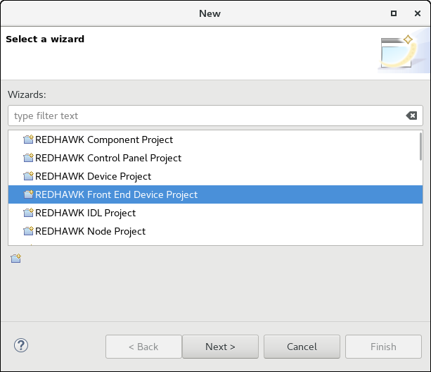
Select a Wizard Page
Select REDHAWK Front End Device Project and click Next.
The Create a REDHAWK Device Project page is displayed:
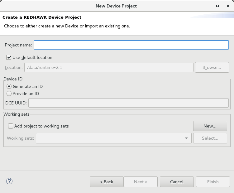
Create a REDHAWK Device Project Page
In the Project name field, enter a project name and click Next.
The New Implementation page is displayed:
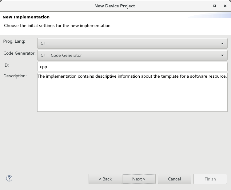
New Implementation Page
Select the programming language; enter a description for this implementation; and click Next.
The Setup Code Generation page is displayed:

Setup Code Generation Page
Click Next.
The FrontEnd Interfaces Device Type Selection page is displayed:
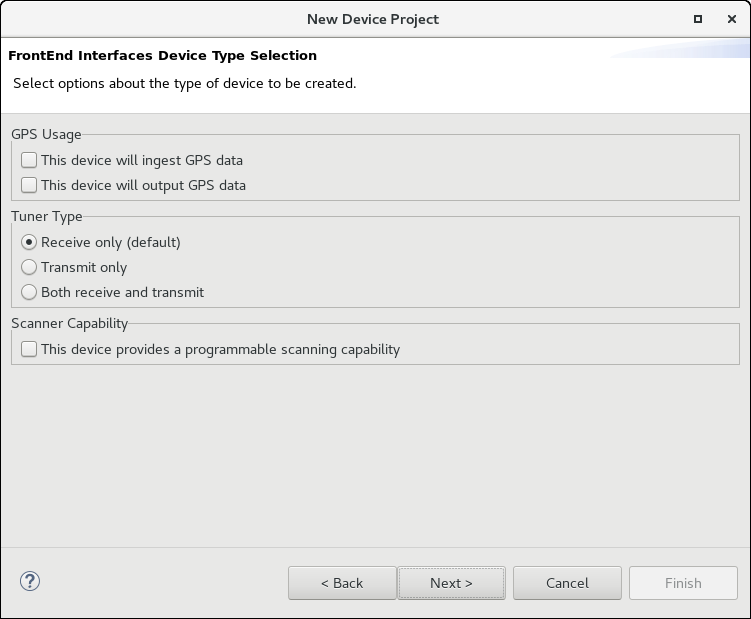
FrontEnd Interfaces Device Type Selection Page
Select the appropriate aspects of the device (needs GPS data or produces GPS data) and its general usage (receive/transmit, scanning capability). Click Next.
The FrontEnd Interface Tuner Options page is displayed:
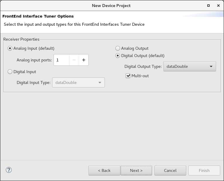
FrontEnd Interface Tuner Options Page
Specify the types of inputs and outputs that the device supports (analog, digital float) and click Next.
The FrontEnd Interfaces Tuner Status Customization page is displayed:
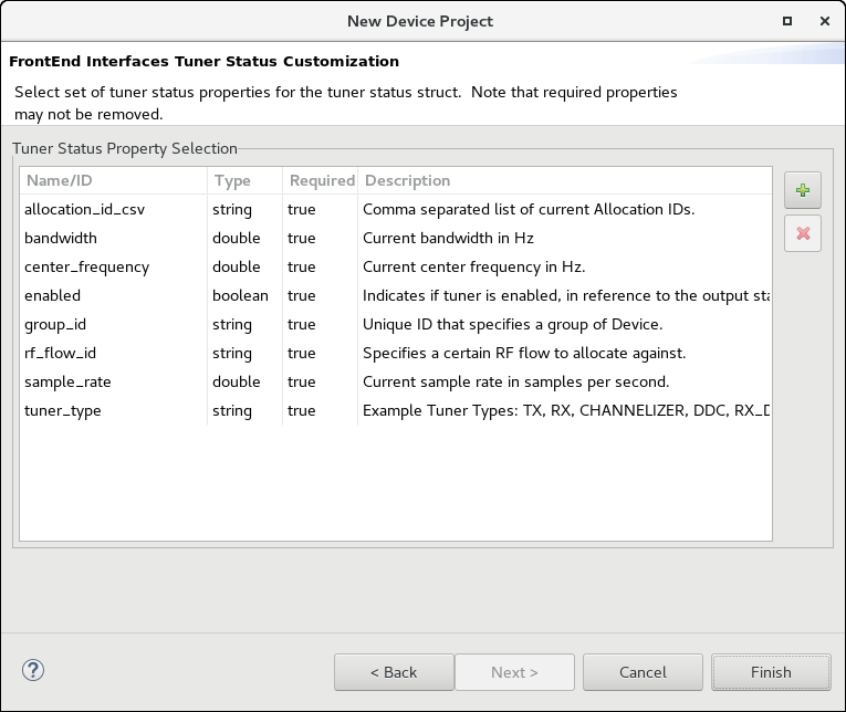
FrontEnd Interfaces Tuner Status Customization Page
- To add an optional tuner status properties, click +, select the checkboxes for the properties, and click OK.
- To remove optional tuner status properties, under Tuner Status Property Selection, select the properties to remove, and click X. If a required property is selected, the X button is disabled.
- Click Finish to exit this wizard.
Upon exiting this wizard,the FEI device project to is created, and the Overview tab of the project is displayed:
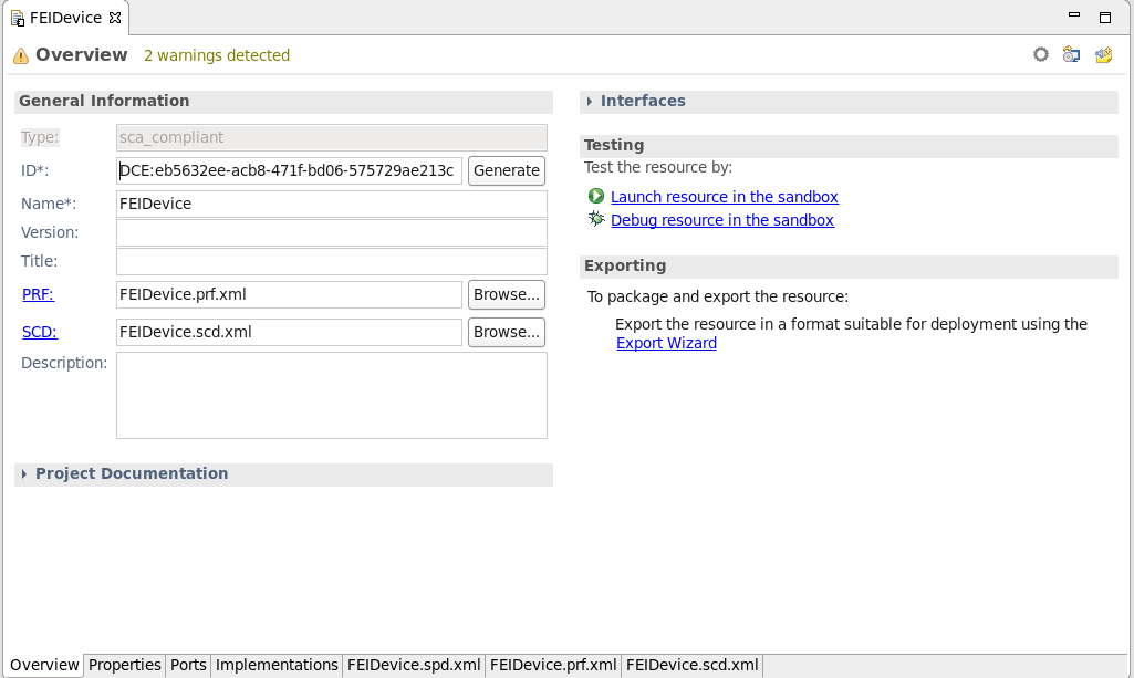
FEI Device Overview Tab
Editing an FEI Device Project
After completing the wizard, you can add ports, properties, and descriptions to an FEI device using the same processes used for all other components and devices. For more information about adding ports, refer to SoftPkg Editor Overview Tab. For more information about adding properties, refer to SoftPkg Editor Properties Tab
For example, it may be useful to add a property used to uniquely identify the target device, such as an IP address.
When editing a FrontEnd Device Project:
- Do not rename properties that were generated using the wizard.
- Do not modify the pre-populated values generated in the wizard (for example, the property,
device_kind). You may, however, add default values to the properties without pre-populated values, such asdevice_model. - Do not change pre-defined FEI Tuner Status properties that were generated in the wizard. You may, however, add user-defined FEI Tuner Status properties.
- Before adding user-defined FEI Tuner Status properties, check to see if relevant pre-defined FEI Tuner Status properties are already available. Use pre-defined FEI Tuner Status properties whenever possible.
To add or remove optional FEI Tuner Status properties using the FrontEnd Interfaces Tuner Status Customization dialog, on the Overview tab of the project, click the Edit FrontEnd properties icon. The same dialog used to define the FEI device’s tuner status property on the creation wizard is displayed. Add or remove the properties and click Finish.
Generating and Customizing the Source Code
This section describes how to generate and customize the source code for an FEI device.
On the Overview tab for the project, click the Generate All Implementations icon to generate the source code.
The Regenerate Files dialog is displayed:
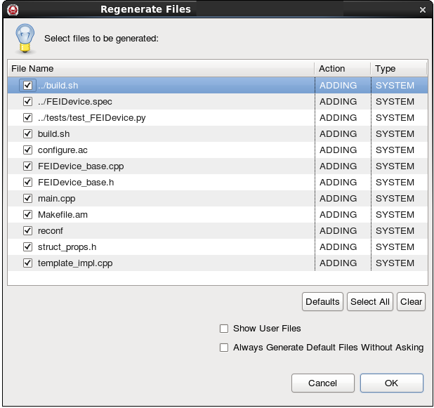
Regenerate Files Dialog
Select the files to be generated and click OK.
Files are generated that define the classes for the FEI device. In C++, the FEI base class inherits from the
frontend::FrontendTunerDeviceclass (orfrontend::FrontendScanningTunerDevicefor a scanner) to provide much of the FEI capability. The generated FEI device class must be modified to interact with the target device. During generation, intentional compiler warnings are inserted in the main class to indicate where code should be modified to reflect the behavior of the device. The output of the make command for a C++ device, including the compiler warnings, is displayed in the Console view: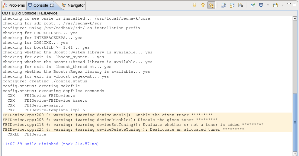
FEI Device Compiler Warnings
There are five functions that contain a default implementation that should be modified to match the desired behavior. These functions are
constructor,deviceEnable,deviceDisable,deviceSetTuning, anddeviceDeleteTuning. Theconstructorfunction is called when the device is instantiated. During allocation of an FEI device,deviceSetTuningis called and, if successful,deviceEnableis called. During deallocation,deviceDisableis called followed by a call todeviceDeleteTuning.For scanners, the additional method
deviceSetTuningScanmust be modified to provide the scanner capability.Add source code to allocate and setup a tuner channel.
The following table explains what is expected in each function/method.
Each of the following functions have
ftsandtuner_idpassed in as parameters. Thetuner_idparameter specifies which tuner channel to operate on, andftsis a reference to the FEI tuner status associated with the specified tuner channel. Additionally,deviceSetTuninghas a parameter calledrequest, which defines the parameters of the tuning request.Functions/Methods in the Generated Code
Function/Method Description constructorThis is the REDHAWK constructor. All properties are initialized prior to this function being invoked. The default behavior when implementing a tuner is to create 1 RX_DIGITIZER channel. deviceEnableCommand the hardware to enable the output and begin generating data. The FEI tuner status element fts.enabledis updated to reflect the current state of the tuner output. This is a good place to callstartto start the service function.deviceDisableCommand the hardware to disable the output and stop generating data. The FEI tuner status element fts.enabledis updated to reflect the current state of the tuner output. This is a good place to callstopto stop the service function.deviceSetTuningWhen an allocation is requested against the FEI device, the base class checks to see which tuners are currently available that match the tuner type (for example, RX_DIGITIZER) and that are currently not set. The base class cycles through this list of available tuners by callingdeviceSetTuningwith a tuner as an argument for the callback. The search is broken whendeviceSetTuningreturns true. For example, if there are ten available tuners,deviceSetTuningcould potentially be called ten times. The tuner is unset when a successful allocation is deallocated;deviceDeleteTuningis the notification that a particular tuner has been deallocated.
There are several helper functions (validateRequest,validateRequestVsSRI,validateRequestVsRFInfo, andvalidateRequestVsDevice) provided in the inheritedFrontendTunerDeviceclass of the device to assist in validation. Then, either configure the hardware with the tuner request, throw aBadParameterExceptionif the request is outside of the capabilities of the tuner, or return false. Update the appropriate FEI tuner status elements (i.e.fts.center_frequency,fts.bandwidth,fts.sample_rate) with the actual values queried from the hardware rather than with the requested values. Push new Signal Related Information (SRI) within this function. Finally, when using the multi-out capability for Bulk Input/Output (BulkIO) ports, it is recommended that thematchAllocationIdToStreamIdfunction be called at this point with the Stream ID and Allocation ID. ReturnTrueupon successful configuration of the tuner according to the request, orFalseotherwise.Additional Functions/Methods in the Generated Scanner Code
Function/Method Description deviceSetTuningScanCalled instead of deviceSetTuningwhen a scanner allocation is made. If the allocation does not contain an accompanying scanning allocation, the function deviceSetTuning is called instead.In addition to the code required for allocation and deallocation, information used to identify the target device at run-time must be added to the main class. The recommended method for dynamically identifying a target device is through configuration of a property. For example, configuring a property with an IP address or some other unique identifier allows the FEI device to identify the specific target device.
Add source code to interact with the target hardware.
There are two key aspects to an FEI device: 1) how many channels does it support? and 2) how does it interact with the hardware?
In an FEI device, the number of channels is set through the
setNumChannelsfunction. By default, this function is included in the generated code with 1 channel. Interaction with the hardware is, obviously, specific to the hardware. The nature of the hardware (i.e.: receiver, transmitter), is specified for the supported channels as the second argument in thesetNumChannelsfunction. For more information, refer to Types of Tuners. By default,setNumChannelsis populated with RX_DIGITIZER, irrespective of the selections made on the FEI wizard.The other aspect of the interaction with hardware is the interaction with the actual driver code. While this interaction is hardware-specific, there are some structures that may be useful. The loop function (
serviceFunctionin C++ and Java,processin Python), is iteratively called after the device is started. As part of thedeviceEnablecallback, callingstarton the device starts processing loop. Conversely, as part of thedeviceDisablecallback, calling thestopon the device stops the processing loop.The tuner interface provides the ability to set parameters like center frequency and bandwith for the receiver. Any FEI compliant device may not output any data until the transients from any receiver setting change have settled to steady state. In short, all data output from an FEI compliant device must correspond to unambiguous receiver settings.
In the service loop function, the implementation of, in the case of a receiver, reading data from the hardware and pushing it out a port would exist. Conversely, in the case of the transmitter, the service loop function would be used to retrieve data from a port and push it through the driver to the hardware.
Add source code to implement FEI-related port functions.
If using an
RFInfoport, it may be useful to store theRFInfopacket as part of the device because it is not stored within the port.For each function on a port definition, a callback is created in the device. This callback takes as arguments the same argument list that is provided by the port function with the exception of the types for the arguments. Where possible, the type for each of the arguments is a C++ type that is easier to use than the corresponding CORBA type. For example, in the case of a string argument, the argument on the port is of type char*, while the argument on the callback is of type std::string&. A thorough description of the different port functions is available in the FEI description.
Scanning Tuners in C++
The scanning tuner can take one of three strategies: manual, span, and discrete. These strategies have been mapped to the C++ device implementation as a set of classes, all inheriting from the ScanStrategy class. Creating a strategy requires instantiating one of these classes. For example, to create a span strategy with a single range from 1 MHz to 1.1 MHz in 10 kHz steps, use the following code:
frontend::ScanSpanRanges ranges;
frontend::ScanSpanRange range;
range.begin_frequency = 1e6;
range.end_frequency = 1.1e6;
range.step = 1e4;
ranges.push_back(range);
frontend::SpanStrategy strat(ranges);
The scan status structure takes ownership of whatever strategy structure it is given. To deal with this issue, strategies can be cloned; the clone function returns a pointer to a new instance of the same strategy. The following example shows how to create a scan status structure with the strategy defined above:
frontend::ScanStatus status(strat.clone());This code is applicable to callbacks for the scanning support functions of the DigitialScanningTuner port such as getScanStatus and setScanStrategy.
Installing the FEI Device
To install the FEI device, build the project and export it to the Target SDR. After the FEI device is installed, you can use it in a REDHAWK system.
Test-running a Sample FEI Device
Create a new FEI project following the steps shown in Using the FEI Wizard to Create an FEI Device. For the purposes of this example, select Python as the language for the device and dataShort as the type for the digital output, otherwise select the defaults on the Wizard for all other settings. Follow steps 1 and 2 in Generating and Customizing the Source Code.
In the deviceEnable function, add the following line:
self.start()In the deviceDisable function, add the following line:
self.stop()In the process function, add the following lines:
data = range(10000)
self.port_dataShort_out.pushPacket(data, bulkio.timestamp.now(), False, "my stream id")
Install and launch the device.
To test-run the device, follow these steps:
In the REDHAWK Explorer tab, expand the Sandbox item.
In the Sandbox item, expand the Device Manager item. The devices running in the sandbox are displayed.
Right-click the device’s output Port (probably called
dataShort_out) and select Plot Port Data.Right-click the running device and and select Allocate. The Allocate Tuner wizard is displayed.
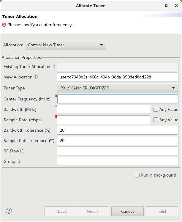
Allocate Tuner Wizard
Enter any arbitrary number in the Center Frequency, Bandwidth, and Sample Rate fields.
To have the wizard perform the allocation as a background job, check the Run in background checkbox. If this checkbox is not checked, the wizard does not close until the allocation is complete.
Click Finish. Data is plotted on the plot.
To stop the flow, right-click the device under the Device Manager item and select Deallocate All. A deallocation warning message is displayed.
Click Yes to confirm that you want to deallocate all.