Waveform Editor
The following sections further describe the definition of the waveform as well as its creation and manipulation within the IDE. Like the Properties File (PRF), Software Component Descriptor (SCD), and Software Package Descriptor (SPD) XML files of a component, a waveform is completely represented by its Software Assembly Descriptor (SAD) file (*.sad.xml). The REDHAWK IDE provides a means of modifying the XML files without the need to directly edit this file by hand.
Overview Tab
Within the Overview tab, the name, Assembly Controller, and external ports of a waveform are defined.
The Assembly Controller is a component instance in the waveform that is designated as the component where the waveform-level start(), stop(), configure(), and query() calls are delegated. In complex waveforms, the Assembly Controller can be used to orchestrate the life cycle of components. In trivial waveforms, the identity of the Assembly Controller is of less importance.
External ports are used to make component ports available to other applications, facilitating inter-application connectivity.
Developers use the Overview tab to set the Assembly Controller for the waveform and describe the waveform.
The following steps explain how to set the Assembly Controller and describe the waveform.
- On the Overview tab of the Waveform, from the Controller drop-down menu, ensure
SigGen_1is selected. - In the Description field, enter a description for the waveform.
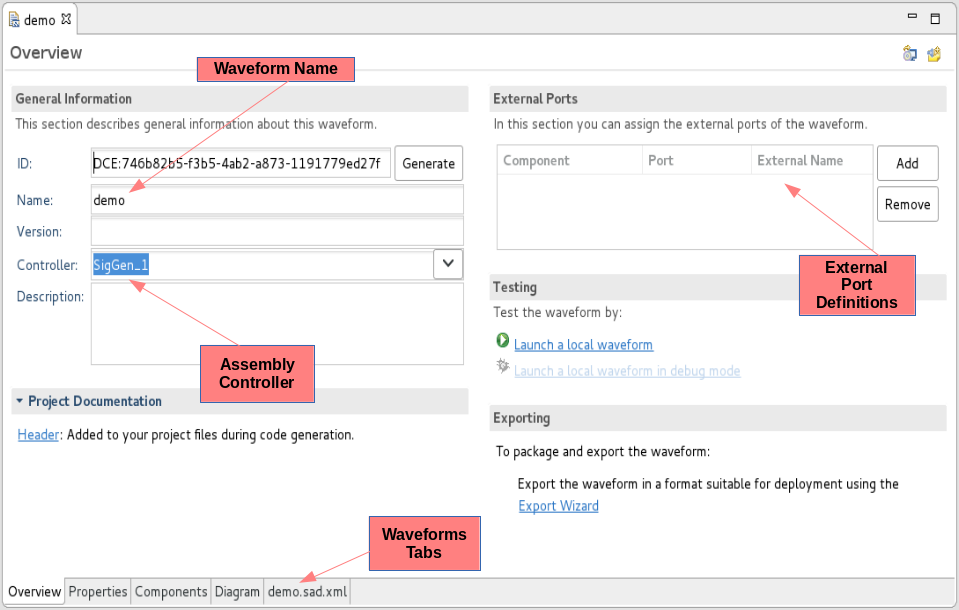
Waveform Overview Tab
Components Tab
The Components tab displays the individual component instantiation elements and their associated details, which can be modified.
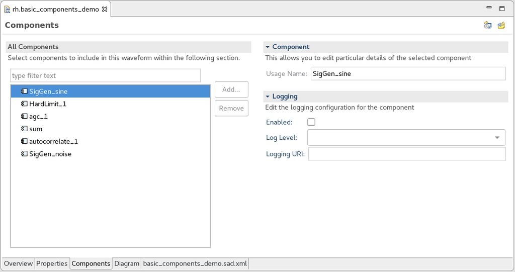
Waveform Components Tab
The All Components section displays all components currently in the waveform as well as Add… and Remove buttons, which can be used to add or remove selected components from the waveform.
The Components section displays the following field, which can be selected to modify the current values:
- Usage Name - Edit the selected component instantiations Usage Name element and Naming Service name, which is based on the component’s usage name.
The Logging section displays the following fields, which can be selected to modify the current values:
- Enabled checkbox - Enable or disable a logging configuration element for the selected component instantiation.
- Log Level combo box - Select predefined logging Levels, including:
OFF,FATAL,ERROR,WARN,INFO,DEBUG,TRACE, andALL. For more information, refer to Logging. - Logging URI - Specify a URI of a logging configuration file.
Diagram Tab
Most of the work done on waveforms takes place within the Diagram tab. The Diagram tab is very similar to the sandbox/Chalkboard. Unlike the sandbox, only components that exist within the $SDRROOT can be added to the waveform. The Palette contains a list of components residing within the $SDRROOT. From the Diagram tab, external ports of the waveform can be indicated and the role of Assembly Controller can be assigned to a component.
Editing Component Properties in a Waveform
From the Diagram tab, properties of components can be set. When these properties are set, they become specific to the waveform and are written to the *.sad.xml file, which describes this waveform.
The following steps explain how to edit the properties of a component in a waveform.
- On the Diagram tab of the waveform, select the component.
- In the Properties view, verify the Properties tab is selected.
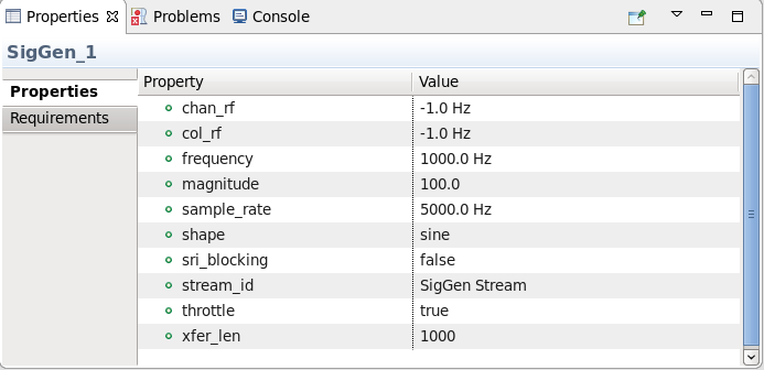
Properties View
- Select the property you want to set, and edit the value.
Editing the devicerequires Set in a Waveform
The devicerequires set for a component is managed through the Requirements tab of the Properties view. When these Requirements are set, they become specific to the waveform and are written to the *.sad.xml file. For more information about the devicrequires set, refer to Binding Components to Executable Devices.
The following steps explain how to edit the devicerequires set.
- On the Diagram tab of the waveform, select the component.
- In the Properties view, verify the Requirements tab is selected.
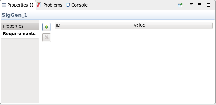
Properties View Requirements Tab
- To add an ID and value, click + and add the ID and value. The ID and value can be any alphanumeric string value. This assigns a
devicerequireskey/value pair to the component. - To remove an ID and value, select the ID and click X.
Start Order
Each of the components within the waveform contain a number with a circle around it which represents that component’s start order. The start order represents the order in which its start() method is called by the Assembly Controller. The only component that does not have a start order is the Assembly Controller, which always has an assumed start order of 0. The Assembly Controller has a yellow circle containing 0. The start order may be changed by right-clicking a component and selecting Move Start Order Earlier or Move Start Order Later from the context menu. The Assembly Controller may be changed by right-clicking a component and selecting Set As Assembly Controller from the context menu.
SAD File Tab
The information displayed in the Overview, Components, and Diagram tabs is represented within the XML of the SAD file. The XML can be edited manually, but it is not recommended. Each of the components used within the waveform are referenced within the SAD file by pointing to the file location of the component’s SPD file.
Instructions for inspecting the SAD file are below:
- Open the
myWaveform.sad.xmltab of the Waveform Editor. - Look through the SAD file and identify:
- The location of the two SPD files used in this waveform (remember that this file location is in reference to the
$SDRROOT) - The Assembly Controller
- The connection between the two components
- The external port is set in the Diagram Tab
- The start order of each component
- The property is changed on the
SigGencomponent
- The location of the two SPD files used in this waveform (remember that this file location is in reference to the
- Before continuing, return to the Diagram tab and change the
dataDouble_outport so that it is no longer marked as an external port.
Application Options
Two options can be set for applications in the SAD file:
STOP_TIMEOUT- controls the time allowed before a timeout occurs. The application’sstopfunction is delegated to each component in the application. In some cases, the component may require an unusually long amount of time to reach a stopped state. To prevent this timeout, configure the application’s option forSTOP_TIMEOUTto the desired value. The default timeout value is 3 seconds. To remove the timeout altogether, set the value to 0 or -1.AWARE_APPLICATION- controls the component’s ability for domain awareness. The default domain awareness value is true. To remove a component’s pointer to the domain, set the optionAWARE_APPLICATIONto false.
To set the application options from the SAD File Overview Tab in the IDE:
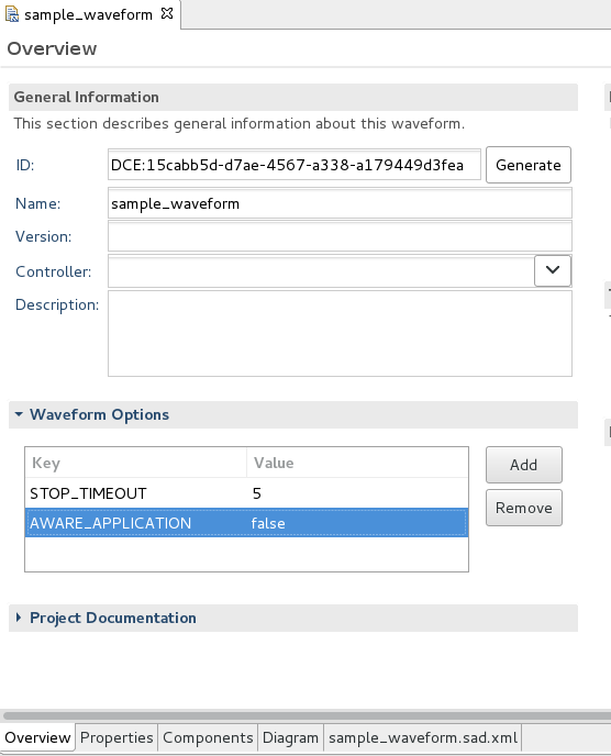
SAD File Overview Tab
- To add an option, expand the waveform Options section, click Add, and enter the value.
- To edit an option, expand the waveform Options section, select the option and edit the value.
- To remove an option, expand the waveform Options section, select the option and click Remove.
To set the application options using a text editor, the options section must follow the connections section in the SAD file.
The following example XML sets the timeout to 5 seconds and the domain awareness to false:
<softwareassembly id="DCE:d67ebd01-d580-47ff-9fe6-5560a9d8f5f8" name="sample_waveform">
  <componentfiles>
    <componentfile id="SigGen_062a14e1-d152-4eb0-b580-821567b323c6" type="SPD">
      <localfile name="/components/rh/SigGen/SigGen.spd.xml"/>
    </componentfile>
  </componentfiles>
  <partitioning>
    <componentplacement>
      <componentfileref refid="SigGen_062a14e1-d152-4eb0-b580-821567b323c6"/>
      <componentinstantiation id="SigGen_1" startorder="0">
        <usagename>SigGen_1</usagename>
        <findcomponent>
          <namingservice name="SigGen_1"/>
        </findcomponent>
      </componentinstantiation>
    </componentplacement>
  </partitioning>
  <assemblycontroller>
    <componentinstantiationref refid="SigGen_1"/>
  </assemblycontroller>
  <connections/>
  <options>
     <option name="STOP_TIMEOUT" value="5"/>
     <option name="AWARE_APPLICATION" value="false"/>
  </options>
</softwareassembly>
The following example Python session sets the timeout to 5 seconds and the domain awareness to false:
>>> from ossie.utils import redhawk
>>> d=redhawk.attach("REDHAWK_DEV")
>>> app=d.createApplication("sample_waveform", initConfiguration={ "STOP_TIMEOUT" : "5" ,  "AWARE_APPLICATION" : "false" } )